Further References and Resources
In addition to the resources provided previously in this book, the following resources are available to provide additional help and guidance to BRL-CAD contributors:
Code Example: Command Plugin
The Geometry Editing Library (libged) defines commands for working with BRL-CAD models. The following code illustrates how individual commands are defined within the library.
#include "common.h"
#include "bio.h"
#include "bu.h"
#include "ged.h"
HIDDEN int
zoom(struct ged *gedp, double sf)
{
    gedp->ged_gvp->gv_scale /= sf;
    if (gedp->ged_gvp->gv_scale < RT_MINVIEWSCALE)
        gedp->ged_gvp->gv_scale = RT_MINVIEWSCALE;
    gedp->ged_gvp->gv_size = 2.0 * gedp->ged_gvp->gv_scale;
    gedp->ged_gvp->gv_isize = 1.0 / gedp->ged_gvp->gv_size;
    ged_view_update(gedp->ged_gvp);

    return GED_OK;
}
int
ged_zoom(struct ged *gedp, int argc, const char *argv[])
{
    int ret;
    double sf = 1.0;

    GED_CHECK_VIEW(gedp, GED_ERROR);
    GED_CHECK_ARGC_GT_0(gedp, argc, GED_ERROR);

    /* must be wanting help */
    if (argc != 2) {
        bu_vls_printf(gedp->ged_result_str, "Usage: %s scale_factor", argv[0]);
        return (argc == 1) ? GED_HELP : GED_ERROR;
    }

    /* get the scale factor */
    ret = bu_sscanf(argv[1], "%lf", &sf);
    if (ret != 1 || sf < SMALL_FASTF || sf > INFINITY) {
        bu_vls_printf(gedp->ged_result_str, "ERROR: bad scale factor [%s]", argv[1]);
        return GED_ERROR;
    }

    return zoom(gedp, sf);
}
Code Example: Walking Geometry
BRL-CAD's models are hierarchical. Primitive shapes are combined with boolean operations into more complex shapes, which are in turn built into even more complex shapes with additional operations. Navigating these hierarchies via tree walking is a standard operation in BRL-CAD.
#include "common.h"
#include "raytrace.h"
/* basically this callback function counts how many CSG nodes are underneath
 * a given combination tree hierarchy.
 */
int
incr_region(struct db_tree_state *tsp, struct db_full_path *pathp, const struct rt_comb_internal *combp, genptr_t data)
{
  int *counter = (int*)data;
  bu_log("...incrementing...\n");
  (*counter)++;
  return 0;
}
int
main(int argc, char *argv[])
{
  struct db_i *dbip;
  int counter = 0;
  struct db_tree_state state = rt_initial_tree_state;

  if (argc < 2) {
    bu_exit(0, "need more, db.g obj\n");
  }

  /* open a .g file for reading */
  dbip = db_open(argv[1], "r");
  if (dbip == NULL) {
    bu_exit(1, "Unable to open %s\n", argv[1]);
  }

  /* build a directory of objects */
  if (db_dirbuild(dbip) < 0) {
    db_close(dbip);
    bu_exit(1, "Unable to load %s\n", argv[1]);
  }

  bu_log("Database title is:\n%s\n", dbip->dbi_title);
  bu_log("Units: %s\n", bu_units_string(dbip->dbi_local2base));

  /* load a particular combination object */
  if (db_lookup(dbip, argv[2], 1) == NULL) {
    db_close(dbip);
    bu_exit(1, "Unable to find %s\n", argv[2]);
  }

  state.ts_dbip = dbip;
  state.ts_resp = &rt_uniresource;
  rt_init_resource( &rt_uniresource, 0, NULL );

  /* walk that combination object's hierarchy,
   * calling our incr_region() callback function.
   * we pass a pointer to our counter variable.
   */
  db_walk_tree(dbip, 1, (const char **)argv+2, 1, &state, incr_region, NULL, NULL, &counter);

  bu_log("counter is %d\n", counter);

  return 0;
}
Working with Our Code
BRL-CAD consists of more than 1 million lines of source code spanning more than 20 foundation libraries and 400 application modules.
The majority of BRL-CAD is written in highly portable C and C++, with some GUI and scripting components written in Tcl/Tk1. There is also some support for, and bindings to, other languages available. POSIX2 shell scripts are used for deployment integration testing. BRL-CAD uses the CMake3 build system for compilation and unit testing.
The Big Picture
The source code and most project data are stored in a Subversion4 version control system for change tracking and collaborative development. Trunk development is generally stable, but cross-platform compilation is not guaranteed. A separate branch (named STABLE) provides a higher level of quality assurance. Every released version of BRL-CAD is tested and tagged.
The project aims for an It Just Works approach to compilation whereby a functional build of BRL-CAD is possible without needing to install more than a compiler, CMake, and a build environment--for example, GNU Make or Microsoft Visual Studio. BRL-CAD provides all of the necessary third-party dependencies for download and compilation convenience within source distributions but by default will build using system versions of those dependencies if available.
As with any large system that has been under development for a number of years, there are vast sections of code that may be unfamiliar, uninteresting, or even daunting. Don't panic. BRL-CAD has been intentionally designed with layering and modularity in mind.
You can generally focus in on the enhancement or change that interests you without being too concerned with other portions of the code. You should, however, do some basic research to make sure what you plan to contribute isn't already in the BRL-CAD code base.
History of the Code
As mentioned previously, the initial architecture and design of BRL-CAD began in 1979. Development as a unified package began in 1983. The first public release was in 1984. And on December 21, 2004, BRL-CAD became an open source project5.
BRL-CAD is a mature code base that has remained active over decades due to continual attention on design and maintainability. Since the project's inception, more than 200 people have directly contributed to BRL-CAD. The project has historically received support from numerous organizations within academia, commercial industry, various government agencies, and from various independent contributors. We credit all contributors in BRL-CAD's authorship documentation6.
The following diagram illustrates how the number of lines of code in BRL-CAD has changed over time:
System Architecture
BRL-CAD is designed based on a UNIX7 methodology of the command-line services, providing many tools that work in harmony to complete a specific task. These tools include geometry and image converters, signal and image processing tools, various raytrace applications, geometry manipulators, and much more.
To support what has grown into a relatively large software system, BRL-CAD takes advantage of a variety of support libraries that encapsulate and simplify application development. At the heart of BRL-CAD is a multi-representation ray tracing library named LIBRT. BRL-CAD specifies its own file format (files with the extension .g or .asc) for storing information on disk. The ray tracing library uses a suite of other libraries for other basic application functionality.
Tenets of Good Software
BRL-CAD's architecture is designed to be as cross-platform and portable as is realistically and reasonably possible. As such, BRL-CAD maintains support for many legacy systems and devices provided that maintaining such support is not a significant burden on new development.
The code adheres to a published change deprecation and obsolescence policy8 whereby features that have been made publicly available are not removed without appropriate notification. Generally there should be a compelling motivation to remove any existing functionality, but improvements are encouraged.
BRL-CAD has a longstanding heritage of maintaining verifiable, validated, and repeatable results in critical portions of the package, particularly in the ray tracing library. BRL-CAD includes regression tests that will compare runtime behavior against known results and report any deviations from previous results as failures. Considerable attention is put into verification and validation throughout BRL-CAD. Incorrect behavior does not need to be preserved simply to maintain consistency, but it is rare to find genuine errors in the baseline testing results. So, anyone proposing such a behavior change will have to conclusively demonstrate that the previous result is incorrect.
Code Layout
The basic layout of BRL-CAD's source code places public API headers in the top-level include directory and source code for both applications and libraries in the src directory. The following is a partial listing of how the code is organized in a checkout or source distribution. Note that some subdirectories contain a README file with more details on the content in that directory.
Applications & Resources
db/
doc/
doc/docbook
- User documentation in XML format
- See doc/docbook/README for more details
include/
regress/
- Scripts and resources for regression testing
src/
- Application and library source code
- See src/README for more details
src/conv/
src/fb/
- Tools for displaying data in windows
src/mged/
- Main GUI application: Multi-device Geometry EDitor
src/other/
- 3rd party frameworks (Tcl/Tk, libpng, zlib, etc.)
src/proc-db/
- Examples on creating models programmatically
src/rt*/
src/util/
- Image processing utilities
Libraries
src/libbn/
- Numerics library: vector/matrix math, random number generators, polynomial math, root solving, noise functions, and more
src/libbu
- Utility library: string handling, logging, threading, memory management, argument processing, container data structures, and more
src/libgcv/
- Geometry conversion library for importing or exporting geometry in various formats
src/libged/
- Geometry editing library containing the majority of our command API
src/libicv/
- Image conversion library for importing, processing, and exporting image data
src/libpkg/
- Network "package" library for basic client-server communication
src/librt/
- Ray tracing library including routines for reading, processing, and writing geometry
src/libwdb/
- Simple (write-only) library for creating geometry
BRL-CAD has a STABLE branch in SVN that should always compile and run on all supported platforms. The primary development branch trunk, unlike STABLE, is generally expected to compile but may occasionally fail to do so during active development.
Languages
The majority of BRL-CAD is written in ANSI/POSIX C with the intent of strictly conforming with the C standard. The core libraries are all C API, though several--such as the LIBBU and LIBRT libraries--use C++ for implementation details. Our C libraries can use C++ for implementation detail, but they cannot expose C++ in the public API.
Major components of the system are written in the following languages:
- STEP and NURBS boundary representation support: C++
- The MGED geometry editor: a combination of C, Tcl/Tk, and Incr Tcl/Tk
- The BRL-CAD Benchmark, build system, and utility scripts: POSIX-compliant Bourne Shell Script
- Initial implementation of a BRL-CAD Geometry Server: PHP
Source code files use the following extensions:
- C files: .c
- Header files: .h
- C++ files: .cpp
- PHP files: .php
- Tcl/Tk files: .tcl or .tk
- POSIX Bourne-style shell scripts: .sh
- Perl files: .pl (program) or .pm (module)
With release 7.0, BRL-CAD has moved forward and worked toward making all of the software's C code conform strictly with the ANSI/ISO standard for C language compilation (ISO/IEC 9899:1990, or c89). Support for older compilers and older K&R-based system facilities is being migrated to build system declarations or preprocessor defines, or is being removed outright. You can, however, make modifications that assume compiler conformance with the ANSI C standard (c89).
Coding Style
To ensure consistency, the coherence of the project, and the long-term maintainability of BRL-CAD, we use a defined coding style and conventions that contributors are expected to follow. Our coding style is documented in the HACKING file of any source distribution.
Our style may not be your preferred style. While we welcome discussion, we will always prefer consistency over any personal preference. Contributions that do not follow our style will generally be rejected until they do.
Here are some highlights of our style:
- Global variables, structures, classes, and other public data containers are discouraged within application code. Do not add any new global variables to existing libraries. Global variables are often a quick solution to some deeper coding problem. However, they carry significant maintenance costs, introduce complexity to the code, make multi-threading support more costly, pollute the public API (symbol-wise at a minimum), increase security risks, are error-prone to use, and usually complicate future efforts to refactor and restructure the code. Using static variables (whether function- or static/file-scoped) is a viable alternative. Restructuring the logic to not be stateful is even better.
- Exact floating point comparisons are unreliable without requiring IEEE-compliant floating point math, but BRL-CAD does not require such math for portability and for performance reasons. When floating point comparisons are necessary, use the NEAR_EQUAL and NEAR_ZERO macros with a specified tolerance or the EQUAL and ZERO macros where a tolerance is indeterminate. All the macros are available by including bn.h, part of libbn.
- The code should strive to achieve conformance with the GNU coding standard with a few exceptions. One such exception is not using the GNU indentation style, but instead using the BSD KNF indentation style, which is basically the K&R indentation style with character indentation consistent with the file that you're editing. If this is confusing, use spaces to indent and run the sh/ws.sh script to convert spaces to tabs. We value consistency to preserve maintainability.
- Stylistic whitespace
No space immediately inside parentheses.
for (i = 0; i < max; i++) { ... /* ok */
while ( max ) { ... /* discouraged */
Commas and semicolons are followed by whitespace.
int main(int argc, char *argv[]); /* ok */
for (i = 0; i < max; i++) { ... /* ok */
No space on arrow operators.
structure->member = 5; /* ok */
structure -> member = 5; /* bad */
Native language statements (if, while, for, switch, and return) have a separating space; functions do not.
int my_function(int i); /* ok, no space */
while (argc--) ... /* ok, has space */
if( var == val ) /* discouraged */
switch(foo) ... /* discouraged */
Comments should have an interior space and be without tabs.
/** good single-line doxygen */
* multiple-line doxygen comment
Variable and public API function names should almost always begin with a lowercase letter.
double localVariable; /* ok */
double LocalVariable; /* bad (looks like class or constructor) */
double _localVar; /* bad (looks like member variable) */
Do not use Hungarian notation or its variations to show the type of a variable. An exception can be made for pointers on occasion. The name should be concise and meaningful--typing a descriptive name is preferred to someone spending time trying to learn what the name of the variable means.
char *pName; /* discouraged for new code, but okay */
Constants should be all upper-case with word boundaries optionally separated by underscores.
static const int MAX_READ = 2; /* ok */
static const int arraySize = 8; /* bad */
Public API (global) function names should be in lowercase with underscores to separate words. Most functions within the core libraries are named with the following convention: [library]_[group]_[action]
Naming exceptions are allowed where the API intentionally mirrors some other familiar programming construct--for example, bu_malloc()+bu_free())--but be as consistent as possible within a file and across a library's API.
- BRL-CAD uses The One True Brace Style from BSD KNF and K&R9. Opening braces should be on the same line as their statement; closing braces should line up with that same statement. Functions, however, are treated specially, and we place their opening braces on separate lines.
for (i = 0; i < 100; i++) {
- http://www.tcl.tk/^
- http://en.wikipedia.org/wiki/POSIX^
- http://www.cmake.org/^
- http://subversion.apache.org/^
- http://developers.slashdot.org/story/05/01/08/1823248/us-army-research-lab-opens-brl-cad-source^
- See the AUTHORS file in a source distribution.^
- http://en.wikipedia.org/wiki/Unix^
- See the CHANGES file in a source distribution.^
- http://en.wikipedia.org/wiki/Indent_style^
Contributing Documentation
Writing and updating BRL-CAD's documentation becomes easier when you understand how to obtain and modify the source files for the documentation.
Note: For more information about creating and modifying documentation, refer to the chapter Working with Our Documentation earlier in this book.
Obtaining the Documentation
The documentation and the toolchain required to generate the documentation is part of the software's development code. You should download the source code from the Subversion version control system using the following command:
svn checkout svn://svn.code.sf.net/p/brlcad/code/brlcad/trunk brlcad-code
The directory brlcad-code should be within your /home directory so that BRL-CAD's build directory commands don't interfere with your system's commands.
Obtaining FOP
While BRL-CAD comes with the tools for generating HTML files and UNIX man pages, you will need additional software to generate PDF files. That software is called Apache FOP, and you can download it from the FOP project's website (http://xmlgraphics.apache.org/fop/). The FOP website also has instructions for installing and configuring FOP to run on your system.
Configure
Next, you must set up the build directory and configure the compilation. This will also set up the tools that you need to generate the documentation. Do that by running the following command.
cmake ../brlcad_build -DBRLCAD_BUILD_TYPE=Debug
Generate the Documentation
Once you've configured the compilation, you'll need to run the following build targets to generate the documentation:
- doc (to generate the HTML version of the documentation and the UNIX man pages)
- html (to generate the HTML version of the documentation)
- man (to generate the UNIX man pages)
- pdf (to generate PDF versions of the documentation. Running this target is optional, and you must have FOP installed on the system on which you're working).
Where to Find the Documentation
You can find the source files for the documentation in the following directories in the BRL-CAD source code repository:
doc/
doc/docbook
- User documentation in XML format
- See the file doc/docbook/README for more details
You can find more information about editing the documentation in the chapter Working with Our Documentation earlier in this book.
Remember to:
- Get in touch with experienced contributors if you have any questions.
- Compile your changes before committing them.
Discussing the Documentation
Before undertaking a documentation task, you should join the BRL-CAD developer mailing list (http://lists.sourceforge.net/lists/listinfo/brlcad-devel) and the #brlcad IRC channel irc.freenode.net.
Joining both lists helps introduce you the the BRL-CAD community and gives you the opportunity to regularly communicate with other experienced contributors. You can also ask questions on the mailing list or the IRC channel.
BRL-CAD contributors have a set of rules that they try to respect and follow to enable collaboration and communication. We strongly encourage new contributors to be creative and to be specific when asking questions on the mailing list or on the IRC channel. We also strongly advise you to use interleaved posting when replying on any communication channels. And once again, don't be afraid to ask questions.
Doc Template: New MGED Command
The following DocBook XML template illustrates the general structure that is used when defining a man page for MGED commands, along with examples of how elements such as paragraphs, lists, and examples are included. If you haven't worked with DocBook before, refer to the section What is DocBook? in the chapter Working with our Documentation.
<refentry xmlns="http://docbook.org/ns/docbook" version="5.0" xml:id="">

<refmeta>
  <refentrytitle> <refentrytitle/>
  <manvolnum>nged</manvolnum>
  <refmiscinfo class="source">BRL-CAD</refmiscinfo>
  <refmiscinfo class="manual">BRL-CAD User Commands</refmiscinfo>
</refmeta>

<refnamediv xml:id="name">
  <refname><refname/>
  <refpurpose>

  </refpurpose>
</refnamediv>
<!-- body begins here -->
<refsynopsisdiv xml:id="synopsis">
  <cmdsynopsis sepchar=" ">
    <command/>
    <arg choice="opt" rep="norepeat"/>
  </cmdsynopsis>
</refsynopsisdiv>
<refsection xml:id="description"><info><title>DESCRIPTION</title></info>
  <para>

  </para>
</refsection>
<refsection xml:id="examples"><info><title>EXAMPLES</title></info>

  <para>

  </para>
  <example><info><title/></info>

    <variablelist>
      <varlistentry>
           <term><prompt/> <userinput/></term>
           <listitem>
             <para>

             </para>
           </listitem>
      </varlistentry>
      <varlistentry>
           <term><prompt/> <userinput/></term>
           <listitem>
             <para>

             </para>
           </listitem>
      </varlistentry>
    </variablelist>
  </example>

  <example><info><title/></info>

    <para>
      <prompt/><userinput/>
    </para>
    <para>

    </para>
  </example>

</refsection>
<info><corpauthor>BRL-CAD Team</corpauthor></info>
<refsection xml:id="bug_reports"><info><title>BUG REPORTS</title></info>
<para>
Reports of bugs or problems should be submitted via electronic
mail to <devs@brlcad.org>, or via the "cadbug.sh" script.
</para>
</refsection>
</refentry>
Example Code: Root Solving
Root solving is (among other things) a key step in the raytracing of many of BRL-CAD's primitives. The following examples illustrate how to solve various types of polynomial equations using BRL-CAD's root solver.
#include "common.h"
#include "bu.h"
#include "vmath.h"
#include "bn.h"
#include "raytrace.h"
int
main(int argc, char *argv[])
{
    bn_poly_t equation; /* holds our polynomial equation */
    bn_complex_t roots[BN_MAX_POLY_DEGREE]; /* stash up to six roots */
    int num_roots;

    if (argc > 1)
        bu_exit(1, "%s: unexpected argument(s)\n", argv[0]);
    /*********************************************
     * Linear polynomial (1st degree equation):
     *  A*X + B = 0
     * [0]   [1]     <= coefficients
     */
    equation.dgr = 1;
    equation.cf[0] = 1;  /* A */
    equation.cf[1] = -2;  /* B */

    /* print the equation */
    bu_log("\n*** LINEAR ***\n");
    bn_pr_poly("Solving for Linear", &equation);
    /* solve for the roots */
    num_roots = rt_poly_roots(&equation, roots, "My Linear Polynomial");
    if (num_roots == 0) {
        bu_log("No roots found!\n");
        return 0;
    } else if (num_roots < 0) {
        bu_log("The root solver failed to converge on a solution\n");
        return 1;
    }

    /*  A*X + B = 0
     *  1*X + -2 = 0
     *    X -  2 = 0
     *    X      = 2
     */
    /* print the roots */
    bu_log("The root should be 2\n");
    bn_pr_roots("My Linear Polynomial", roots, num_roots);
    /*********************************************
     * Quadratic polynomial (2nd degree equation):
     *  A*X^2 + B*X + C = 0
     * [0]     [1]   [2]     <=coefficients
     */
    equation.dgr = 2;
    equation.cf[0] = 1;  /* A */
    equation.cf[1] = 0;  /* B */
    equation.cf[2] = -4; /* C */

    /* print the equation */
    bu_log("\n*** QUADRATIC ***\n");
    bn_pr_poly("Solving for Quadratic", &equation);

    /* solve for the roots */
    num_roots = rt_poly_roots(&equation, roots, "My Quadratic Polynomial");
    if (num_roots == 0) {
        bu_log("No roots found!\n");
        return 0;
    } else if (num_roots < 0) {
        bu_log("The root solver failed to converge on a solution\n");
        return 1;
    }

    /*  A*X^2 + B*X +  C = 0
     *  1*X^2 + 0*X + -4 = 0
     *    X^2       -  4 = 0
     * (X - 2) * (X + 2) = 0
     *  X - 2 = 0, X + 2 = 0
     *  X = 2, X = -2
     */
    /* print the roots */
    bu_log("The roots should be 2 and -2\n");
    bn_pr_roots("My Quadratic Polynomial", roots, num_roots);
    /*****************************************
     * Cubic polynomial (3rd degree equation):
     *  A*X^3 + B*X^2 + C*X + D = 0
     * [0]     [1]     [2]   [3]     <=coefficients
     */
    equation.dgr = 3;
    equation.cf[0] = 45;
    equation.cf[1] = 24;
    equation.cf[2] = -7;
    equation.cf[3] = -2;

    /* print the equation */
    bu_log("\n*** CUBIC ***\n");
    bn_pr_poly("Solving for Cubic", &equation);

    /* solve for the roots */
    num_roots = rt_poly_roots(&equation, roots, "My Cubic Polynomial");
    if (num_roots == 0) {
        bu_log("No roots found!\n");
        return 0;
    } else if (num_roots < 0) {
        bu_log("The root solver failed to converge on a solution\n");
        return 1;
    }

    /* print the roots */
    bu_log("The roots should be 1/3, -1/5, and -2/3\n");
    bn_pr_roots("My Cubic Polynomial", roots, num_roots);
    /*******************************************
     * Quartic polynomial (4th degree equation):
     *  A*X^4 + B*X^3 + C*X^2 + D*X + E = 0
     * [0]     [1]     [2]     [3]   [4]     <=coefficients
     */
    equation.dgr = 4;
    equation.cf[0] = 2;
    equation.cf[1] = 4;
    equation.cf[2] = -26;
    equation.cf[3] = -28;
    equation.cf[4] = 48;

    /* print the equation */
    bu_log("\n*** QUARTIC ***\n");
    bn_pr_poly("Solving for Quartic", &equation);

    /* solve for the roots */
    num_roots = rt_poly_roots(&equation, roots, "My Quartic Polynomial");
    if (num_roots == 0) {
        bu_log("No roots found!\n");
        return 0;
    } else if (num_roots < 0) {
        bu_log("The root solver failed to converge on a solution\n");
        return 1;
    }
    /* print the roots */
    bu_log("The roots should be 3, 1, -2, -4\n");
    bn_pr_roots("My Quartic Polynomial", roots, num_roots);
    /*******************************************
     * Sextic polynomial (6th degree equation):
     *  A*X^6 + B*X^5 + C*X^4 + D*X^3 + E*X^2 + F*X + G = 0
     * [0]     [1]     [2]     [3]     [4]     [5]   [6]  <=coefficients
     */

    equation.dgr = 6;
    equation.cf[0] = 1;
    equation.cf[1] = -8;
    equation.cf[2] = 32;
    equation.cf[3] = -78;
    equation.cf[4] = 121;
    equation.cf[5] = -110;
    equation.cf[6] = 50;

    /* print the equation */
    bu_log("\n*** SEXTIC ***\n");
    bn_pr_poly("Solving for Sextic", &equation);

    /* solve for the roots */
    num_roots = rt_poly_roots(&equation, roots, "My Sextic Polynomial");
    if (num_roots == 0) {
        bu_log("No roots found!\n");
        return 0;
    } else if (num_roots < 0) {
        bu_log("The root solver failed to converge on a solution\n");
        return 1;
    }

    /* print the roots */
    bu_log("The roots should be 1 - i, 1 + i, 2 - i,2 + i, 1 - 2*i, 1 + 2*i \n");
    bn_pr_roots("My Sextic Polynomial", roots, num_roots);

    return 0;
}
Feature Overview
BRL-CAD has thousands of distinct features that have been developed over a number of decades. One strength of a solid modeling system with integrated high-performance rendering is the ability to showcase some of those features graphically.
Let's take a quick look at just some of the high-level features provided by BRL-CAD.
Solid Geometry
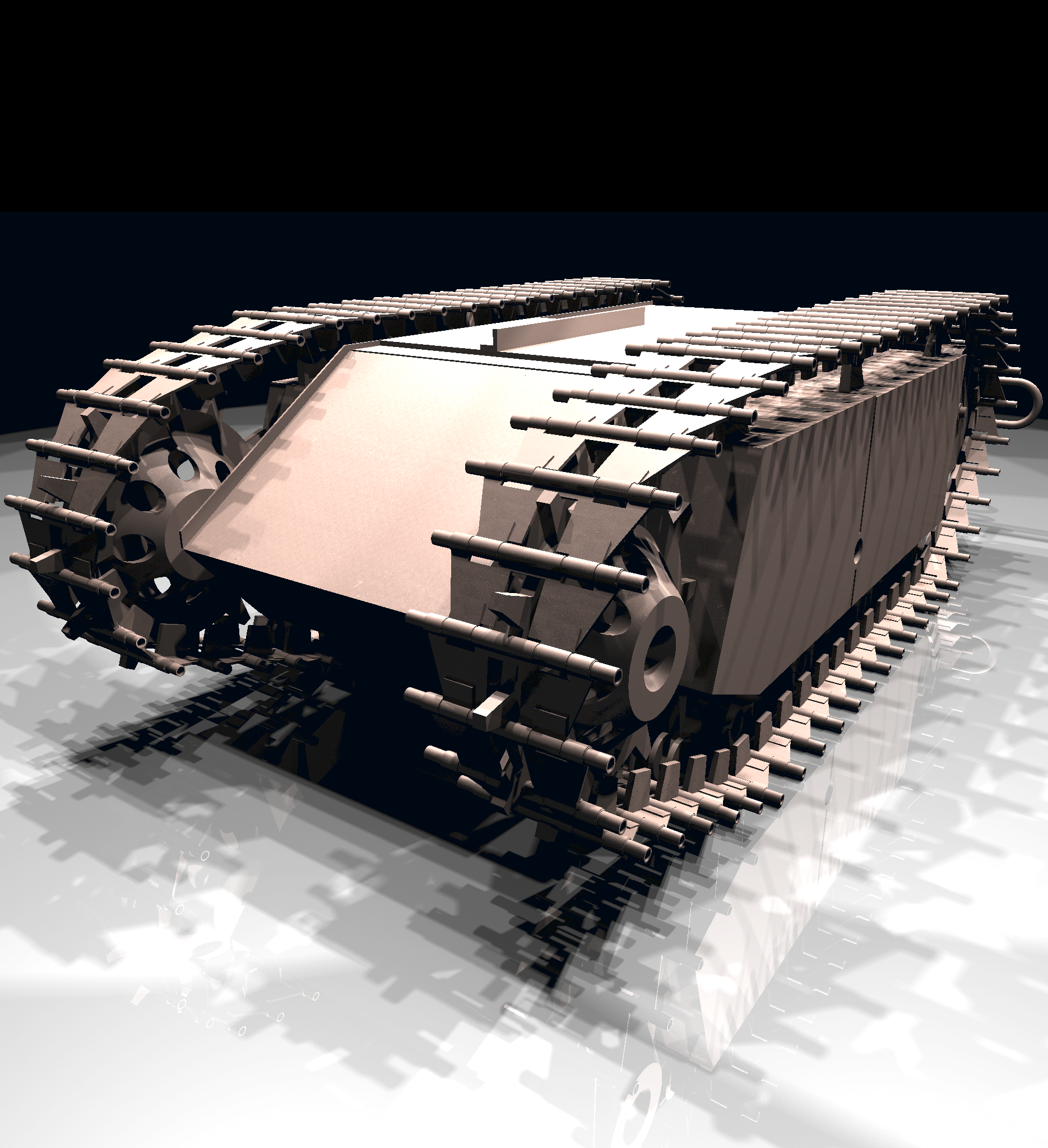
BRL-CAD focuses on solid modeling CAD. Solid modeling is distinguished from other forms of geometric modeling by an emphasis on being physically accurate, fully describing 3D space. Shown is a 3D model of a Goliath tracked mine, a German-engineered remote controlled vehicle used during World War II. This model was created by students new to BRL-CAD in the span of about 2 weeks, starting from actual measurements in a museum.
Raytracing
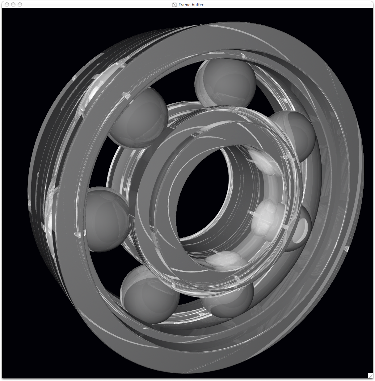
Raytracing is central to BRL-CAD as a means for performing geometric analysis (e.g., calculating weights and moments of inertia) and for rendering images for visualization purposes. The image shown is a BRL-CAD 2D framebuffer screenshot displaying the rendering of a ball bearing. The bearing is modeled with a material appearance resembling acrylic glass, and this raytracing result shows reflection, refraction, shadowing, and some caustic effects.
Geometry Conversion
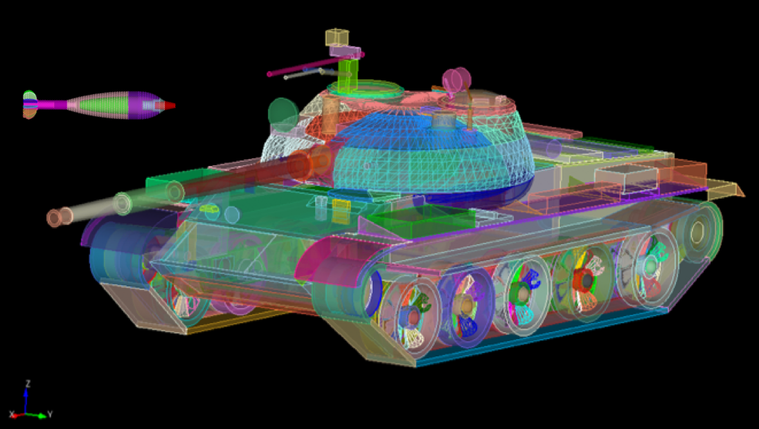
As shown, a BRL-CAD target description can be converted to a finite element mesh (FEM) using the BRL-CAD g-sat exporter and Cubit from Sandia National Laboratories.
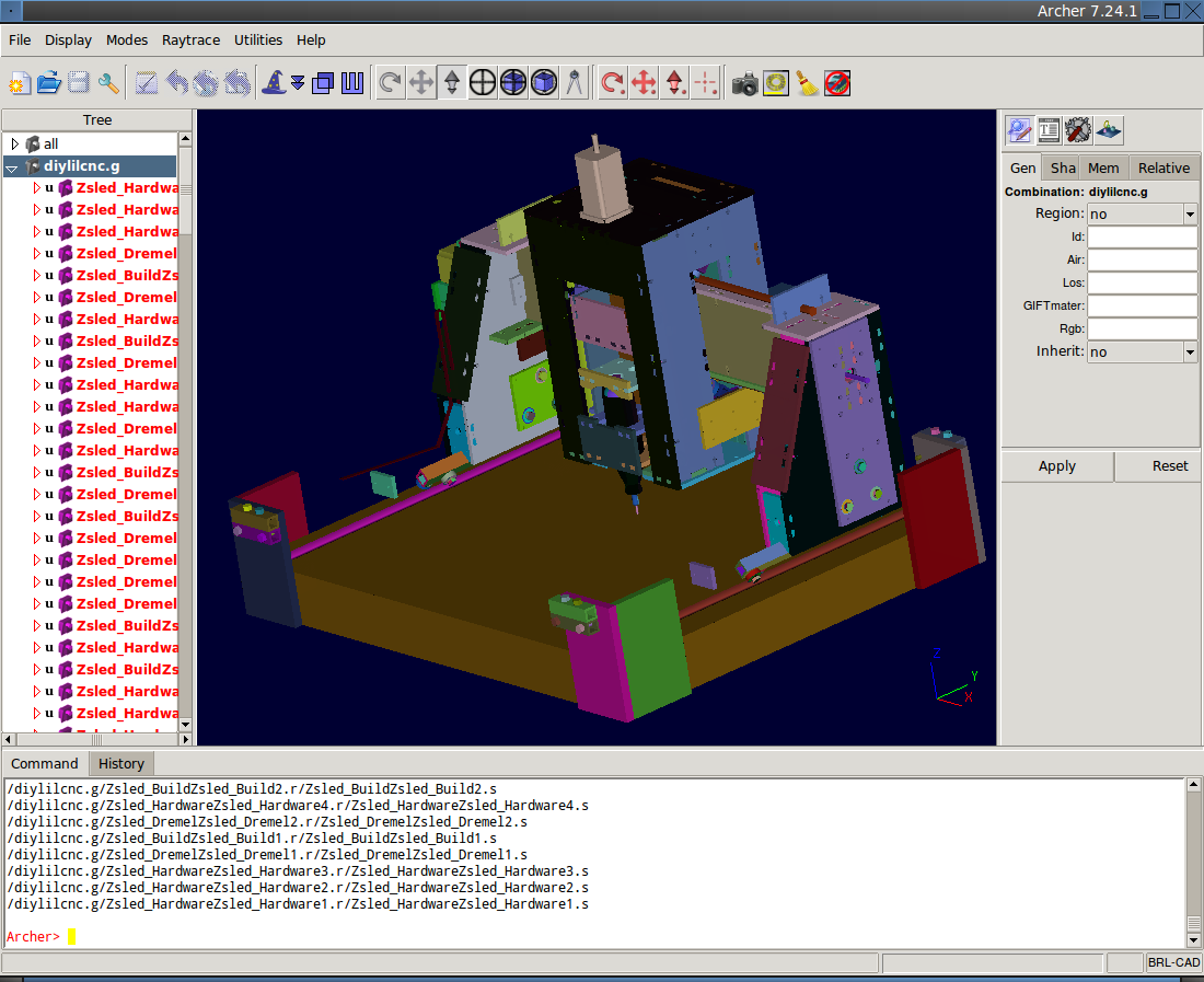
This screenshot shows a model imported from the Rhino3D 3DM file format into BRL-CAD as NURBS boundary representation geometry, visualized via OpenGL.
Procedural Geometry
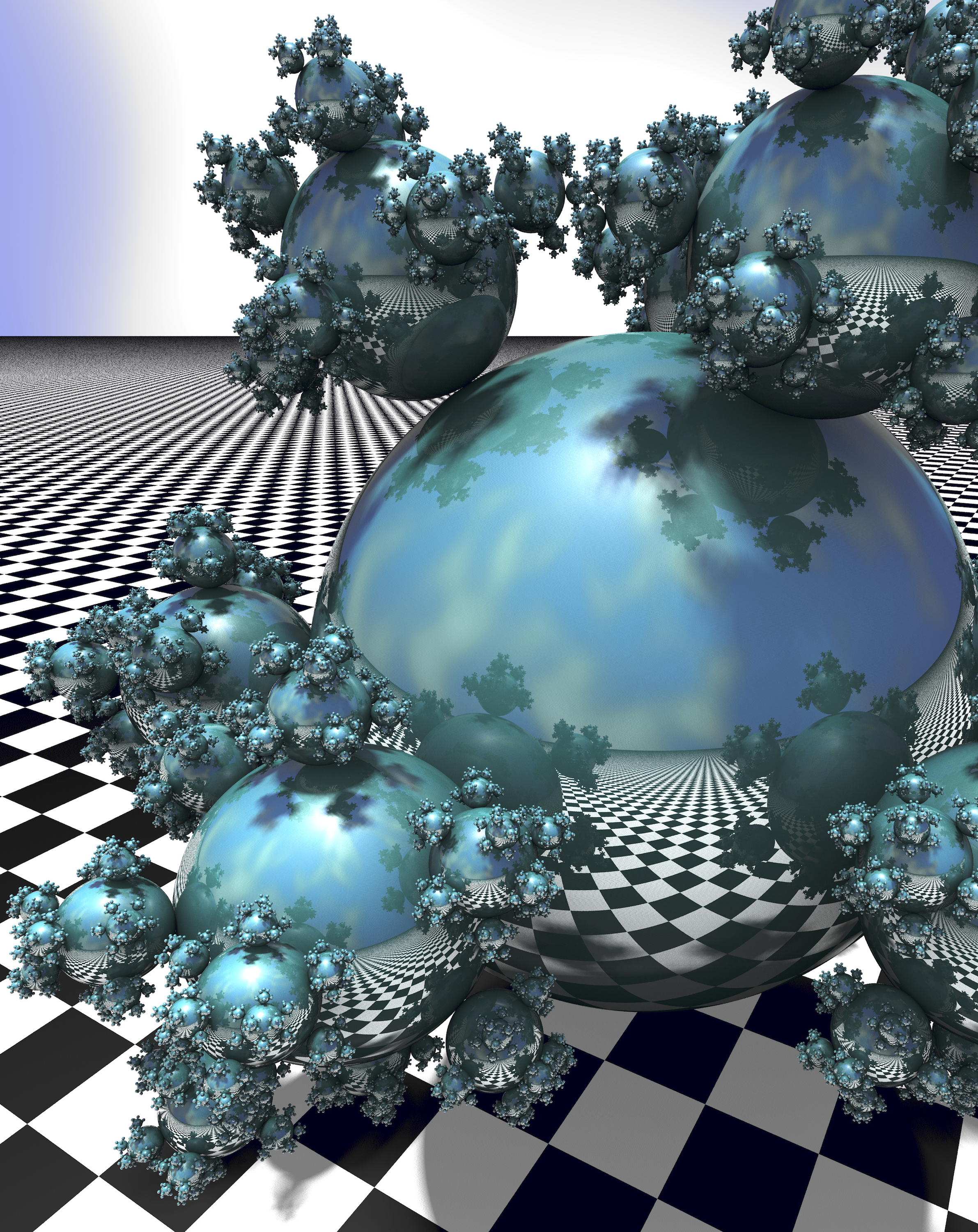
BRL-CAD provides a comprehensive procedural geometry interface as a means for creating models algorithmically instead of manually. This screenshot shows a classic "Sphere Flake" model with five levels of recursion, specular reflections, multiple light sources, environment mapping, checkered texture synthesis, ambient occlusion, and soft shadows.
Boundary Representation

Boundary representation NURBS surface geometry is one of the dominant geometric representation formats in CAD. BRL-CAD is one of the few 3D solid modeling systems that not only support geometry in boundary representation NURBS format but also provide extensive support for robust solid ray tracing of NURBS geometry. The image shown is the classic computer graphics Utah teapot model prepared for 3D printing and rendered via BRL-CAD ray tracing.
Path Tracing
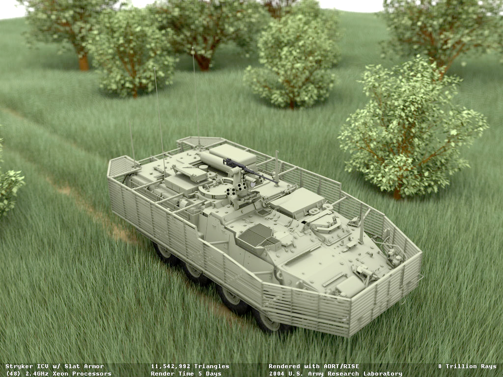
Representing more than 8 trillion rays fired at this 11-million-polygon scene (amounting to more than 20 million rays per second on 2004 hardware), this figure signifies the path tracing capability of BRL-CAD. A full light simulation was computed to generate the image with all exterior and interior vehicle detail, including every nut, bolt, wire, and component inside the vehicle and every leaf and blade of grass modeled as actual geometry (with no textures and no procedural geometry).
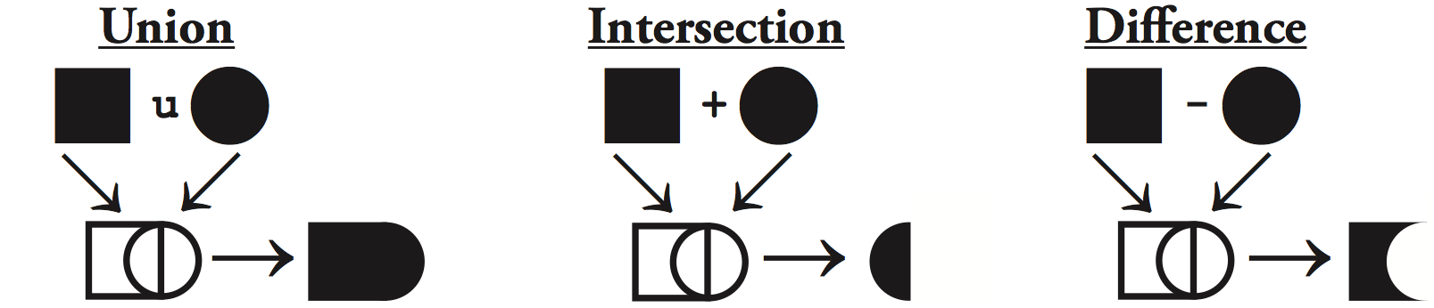
Constructive Solid Geometry (CSG)
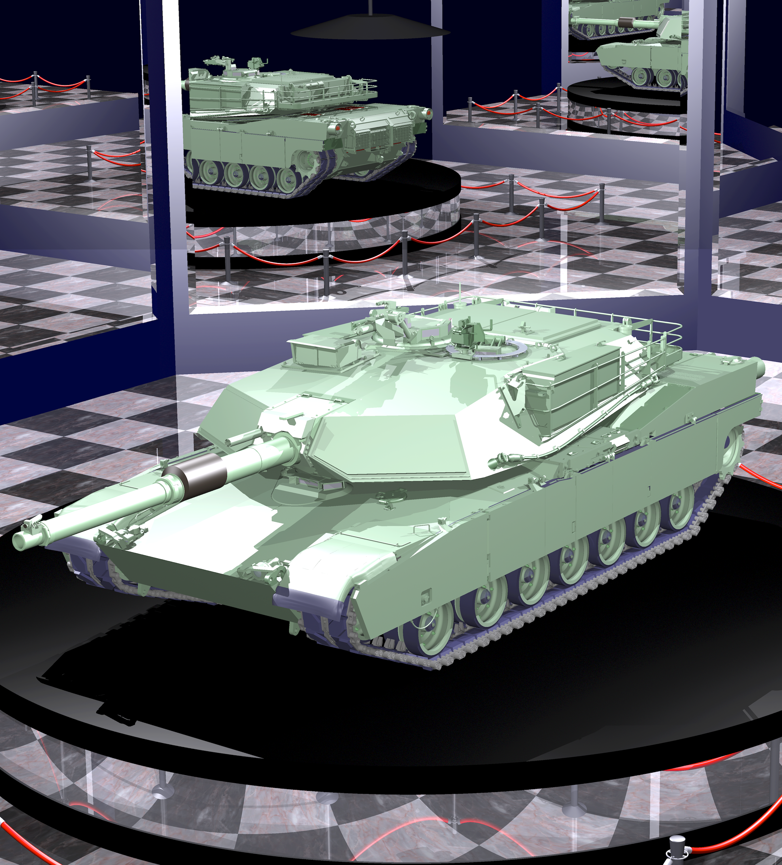
While now a fully hybrid modeling system, BRL-CAD has its roots in CSG modeling with implicit primitives. This image, provided courtesy of GSI Solutions, Inc., depicts a detailed M1A1 tank on a pedestal in a mirrored showcase room. The model is entirely constructed from implicit primitives and CSG boolean operations.
Hidden Line Rendering
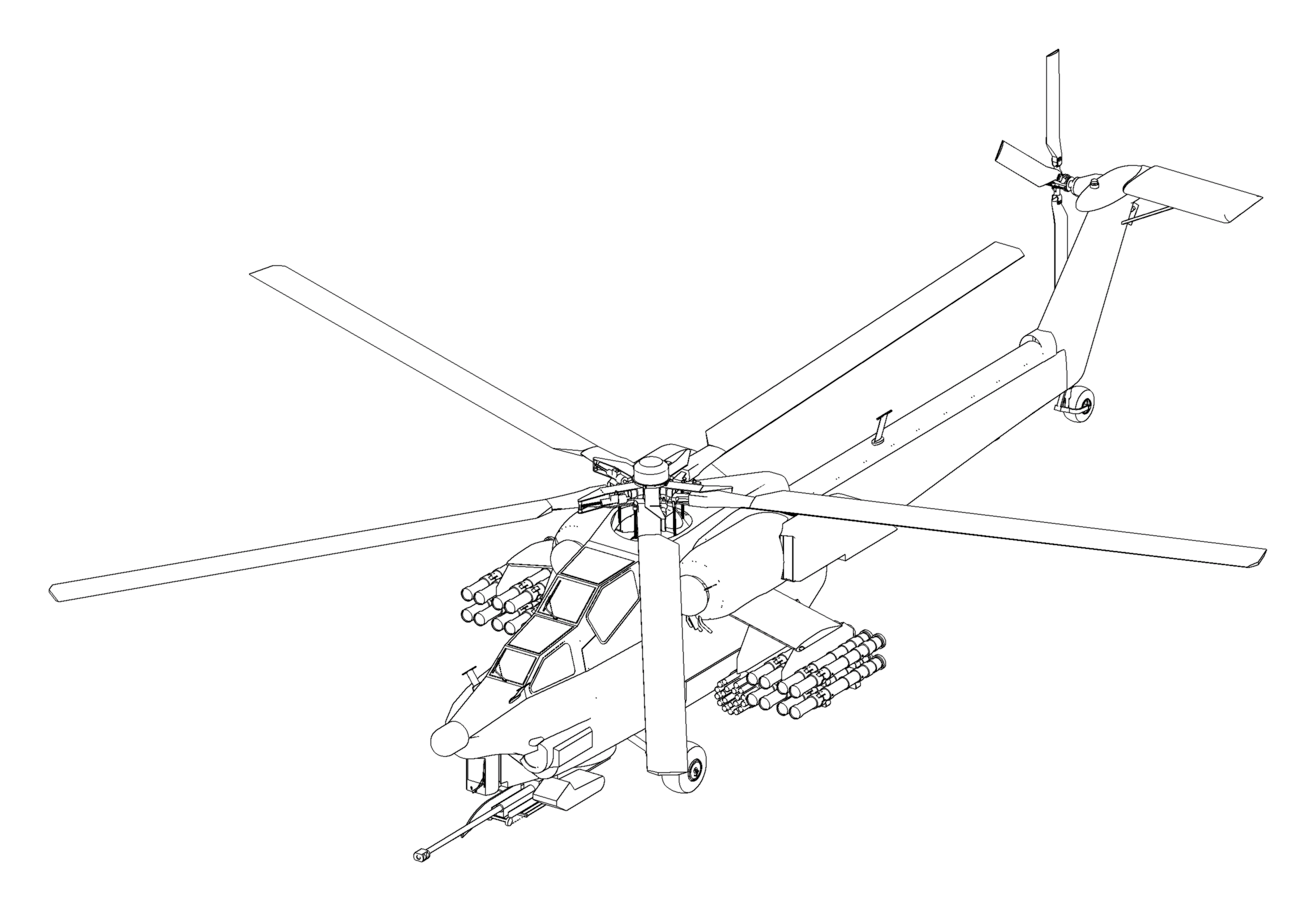
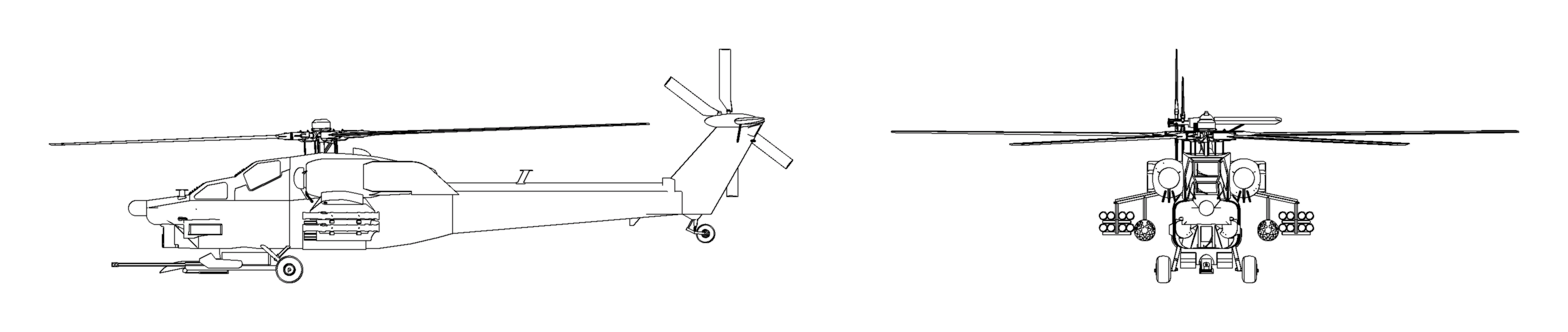
This raytrace image is a multiple-view hidden line rendering of an Mi28 Havoc Russian attack helicopter using BRL-CAD's rtedge utility. The model is entirely composed of implicit primitives combined together with CSG boolean operations.
Scripting Interface
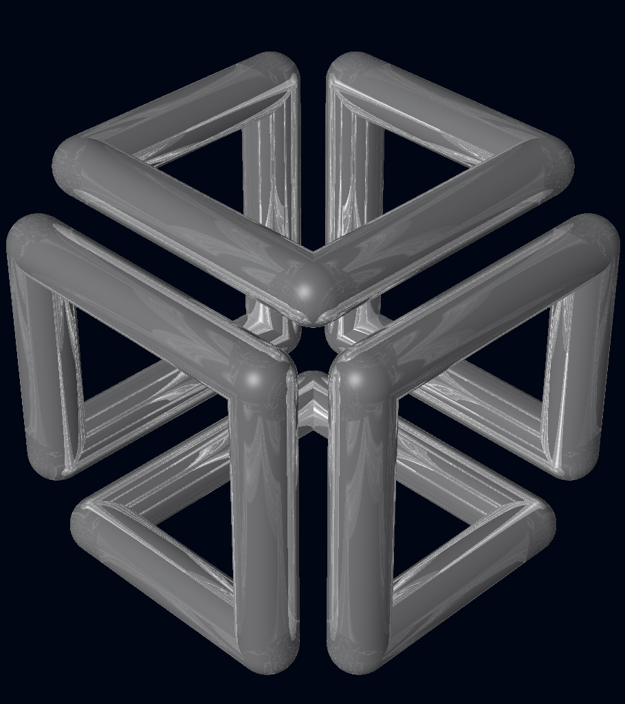
BRL-CAD can run series of commands piped in or redirected to it via standard input, and it is considerably more efficient to batch multiple BRL-CAD commands together via standard input instead of re-invoking BRL-CAD for each command. The image demonstrates the output of a shell script that uses BRL-CAD tools to procedurally create and render the SGI Cube. For more information, go to http://brlcad.org/wiki/SGI_Cube.
More Cowbell
Not all of BRL-CAD's capabilities lend themselves well to pretty pictures, but some are definitely worth mentioning. Among the thousands of features in BRL-CAD, here are some additional capabilities that are central to our project ethos.
Geometric Analysis
A particular strength of the BRL-CAD software lies in its ability to build and analyze realistic models of complex objects. There are a number of features aimed at inspecting, preparing, verifying, and validating geometry models. Single-ray sampling can be used for measuring thicknesses or distances, and certain 3D analyses are possible (such as calculating volume, centroids, and moments of inertia). BRL-CAD also has numerous facilities for detecting and resolving assembly or part interferences where two objects spatially overlap each other.
High-Performance Design
BRL-CAD is designed from the ground up with performance in mind. Considerable attention has been put into in-memory and on-disk data storage efficiency. BRL-CAD is capable of handling complex geometry models that are often impossible to open with other systems without changing hardware requirements. BRL-CAD's ray tracing infrastructure is one of the fastest in the world for implicit geometry representations and is continually seeking performance advancements for other explicit representation types, such as polygonal mesh geometry and NURBS surface models. BRL-CAD's distributed ray tracing support is recognized as the world's first "real-time" ray tracing implementation, achieving several frames per second in the 1980s.
Symmetric Multi-Processing
BRL-CAD efficiently leverages symmetric multi-processing (SMP) capabilities of desktop, server, and supercomputing systems, where an arbitrary number of processing cores can be put to work on a computational task. BRL-CAD's ray tracing library is commonly leveraged for performing highly detailed geometric analysis, driving third-party simulations, and producing animations.
Modular Architecture
As a large software package developed over a relatively long period of time, BRL-CAD has necessarily been designed and evolved with modularity in mind. Functionality is implemented across hundreds of application modules, commands, and libraries designed to work together. Hundreds of application binaries work together supporting efficient customizable workflows. Core geometry editing capabilities are implemented as commands that can be easily extended, replaced, or improved upon. All functionality and features are built on top of a core set of libraries that encapsulate common capabilities. One of the best ways to get involved is to add a new module or improve an existing one.
Cross-Platform Portability
BRL-CAD has an extensive history of investment in and attention toward cross-platform portability. This heritage includes systems such as a DEC VAX-11/780 running 4.3 BSD, DECStations running ULTRIX, Silicon Graphics machines running IRIX, Cray supercomputers running UNICOS, and so much more. Today, BRL-CAD's hardware support includes everything from minimal laptops and desktops to gigantic distributed supercomputers. And it is commonly run on Linux, Windows, Mac OS X, BSD, Haiku, Solaris, and other desktop operating systems. We aim to be "embarrassingly portable."
ISO STEP 10303
STandard for the Exchange of Product Model Data (STEP) is an ISO standard describing a product's full life cycle. One small portion of that gigantic standard describes a complex geometry file format that fortunately has been adopted by most commercial CAD systems. BRL-CAD is proud to be one of the few open source software systems that is able to read and write STEP geometry files.
Performance Benchmark
The BRL-CAD Benchmark provides a practical metric of real-world performance. Correlated with a longstanding heritage of providing verifiable and repeatable behavior throughout the package, the Benchmark compares a given compilation's ray tracing performance against the results from one of the very first systems to support BRL-CAD: a VAX 11/780 running BSD. The mathematically intensive computations exercise the processing unit, system memory, various levels of data and instruction cache, the operating system, thread concurrency efficiency, data coherency, and compiler optimization capabilities. The performance results let you weigh the relative computational strength of a given platform. With the right controls in place, the Benchmark can tell you whether a given operating system is more efficient than another, whether a particular compiler really makes a difference, or just how much of an improvement a particular piece of hardware provides. We have results tracing back several decades of computing.
Working with Our Documentation
BRL-CAD provides documentation in the following formats:
- UNIX man pages.
- HyperText Markup Language (HTML) for the web.
- PDF for documents needing a well-defined, consistent appearance.
Our challenge is to maintain BRL-CAD's documentation in multiple formats. It is difficult enough to keep software documentation up to date without needing to update multiple documents using different formats that contain the same information. As well, it is not possible to supply documentation in a single format that works optimally on all platforms. For example, while UNIX man pages are standard across all UNIX and UNIX-like systems, most Windows systems will not understand that format and will require HTML versions of those documents.
Instead of using a mix of formats and tools, BRL-CAD uses the DocBook documentation format and toolchain to produce documentation in the range of required formats.
What is DocBook?
DocBook is a schema (a structured approach to organization of information) that uses the eXtensible Markup Language standard (XML) as its fundamental framework and builds atop that framework a vocabulary for describing the content and structure of technical documentation. BRL-CAD uses the DocBook 5.0 documentation format to describe its documentation. For detailed documentation for DocBook 5.0, see http://www.docbook.org/tdg5/en/html/docbook.html.
Tools for Working with DocBook
While you can write documentation in DocBook using WYSIWYG (What You See Is What You Get) editors, we require that a document saved to DocBook from an editing tool should be inspected for human readability and, if necessary, reformatted for simplicity.
If you are comfortable with working with DocBook XML directly, we recommend that you use the Emacs editor and its nXML module. nXML can automatically recognize and highlight mistakes in the structure of a document while you are editing. The following image illustrates nXML identifying an incorrect closing tag for an informal figure object:
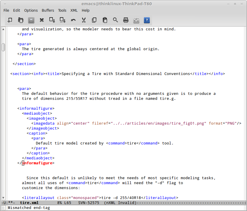
Aside from error checking tools like nXML, the ability to pinpoint errors in a document's formatting is built into the BRL-CAD compilation process. That process uses a tool called xmllint to report incorrect formatting. When, for example, the error illustrated in the image above is encountered during BRL-CAD's build, xmllint produces the following error:
[40%] Validating DocBook source with xmllint:
/home/user/brlcad/doc/docbook/articles/en/tire.xml:65: parser error : Opening and ending tag mismatch: informalfigure line 54 and informafigure
</informafigure>
^
CMake Error at tire_validate.cmake:39 (message):
xmllint failure: 1
In this case, the error is reasonably informative. However, xmllint is not the only tool available for this sort of error checking. You can specify the following validation tools when you configure your environment:
Note that these alternative validation tools must be installed on the system on which you are working; they are not provided with BRL-CAD. To specify an alternative tool, use the VALIDATE_EXECUTABLE option. For example, run the following command to use the Oracle Multi-Schema XML Validator:
cmake -DVALIDATE_EXECUTABLE=msv ...
While BRL-CAD provides enough DocBook support to guarantee that HTML files and UNIX man pages are generated, you can only generate PDF documents if the Apache Formatting Objects Processor (FOP) (http://xmlgraphics.apache.org/fop) is installed on your system. When FOP is available, BRL-CAD can automatically produce PDF outputs.
For more information, including how to use alternative tools for other DocBook processing steps besides validation, see the file doc/docbook/README in the BRL-CAD source code archive.
Adding a New Document to BRL-CAD
Because creating and editing DocBook documentation is greatly simplified by BRL-CAD's management of the conversion process, it is usually a good idea to add a new document to the build system at the beginning of the document creation and editing process. To do this, copy a template file from the source directories to the file name to be used for the new document.
For example, if you are writing a new DocBook article in English about the ellipsoid, use the following command to copy the article template to the filename ellipsoid.xml in the English articles directory:
~/brlcad $ cp doc/docbook/articles/en/TEMPLATE.xml doc/docbook/articles/en/ellipsoid.xml
Next, open the file doc/docbook/articles/en/CMakeLists.txt in a text editor. Then, add the name of the new document to the file to alert the build system of its existence:
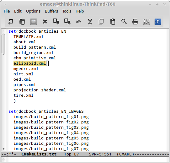
BRL-CAD now knows about the new file and can generate output for it.
You will generally only want to rebuild a specific output (say, HTML) to confirm that output renders properly. To set up the specific targets for the new file, run the command below to refresh the build targets (in this example, the build output directory is called build):
~/brlcad/build $ cmake ..
This creates a new build target, ellipsoid_article_html, which will build only the HTML output of the document and its dependencies:
~/brlcad/build $ make ellipsoid_article_html
[ 0%] Built target printtimestamp
[ 0%] Built target buildtimestart
Build Time: Tue Oct 15 19:14:42 2013
[ 0%] Built target timestamp
[ 0%] Built target zlib
[100%] Built target xml
[100%] Built target xslt
[100%] Built target exslt
[100%] Built target xmllint
[100%] Built target xsltproc
[100%] Built target schema-expand
[100%] Built target fonts-dejavu-expand
[100%] Built target fonts-stix-expand
[100%] Built target offo-2-expand
[100%] Built target svg-dtd-expand
[100%] Built target xsl-expand
[100%] Built target docbook_articles_EN_IMAGES_cp
Scanning dependencies of target ellipsoid_article_html
[100%] Validating DocBook source with xmllint:
/home/cyapp/brlcad/doc/docbook/articles/en/ellipsoid.xml validates
[100%] Generating ../../../../share/doc/html/articles/en/ellipsoid.html
[100%] Built target ellipsoid_article_html
~/brlcad/build $
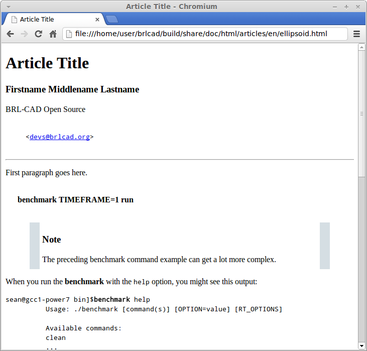
This generates a file named brlcad/build/share/doc/html/articles/en/ellipsoid.html. Open this document in a web browser to view the HTML output:
Now that all the pieces are in place, you can begin the documentation cycle:
- Modify the DocBook XML sources.
- Build the HTML output. As long as the DocBook file is the only file being changed, you can use the target ellipsoid_article_html/fast to avoid checking the target's dependencies and to speed up the compilation process.
- Once you have generated the updated HTML file, refresh the page in your web browser to view the changes.
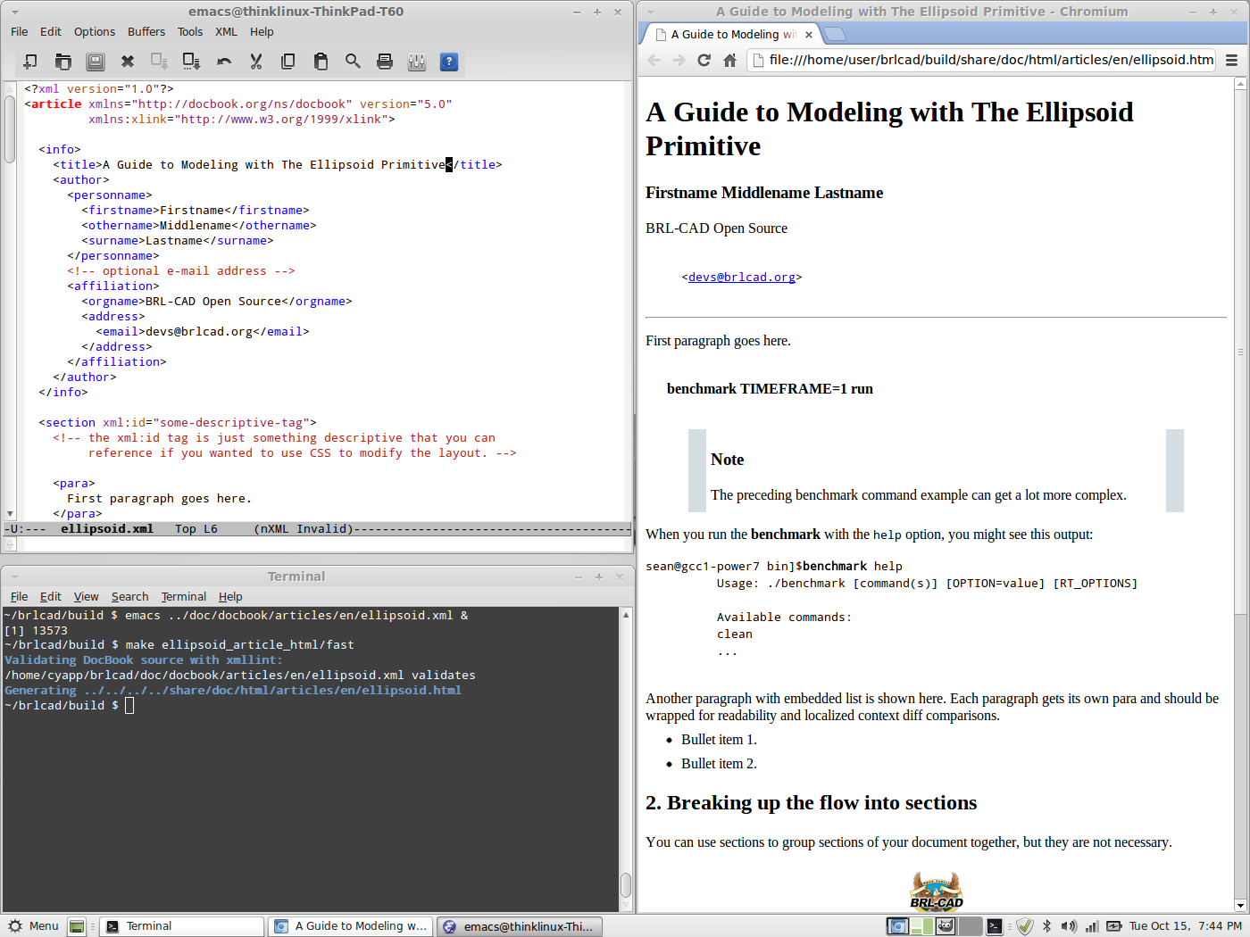
In the following example, all of the previous elements are combined into a DocBook editing workflow. The title of the article was changed from the default (Article Title) to the article's actual title (A Guide to Modeling with the Ellipsoid Primitive), the build target was remade, and the results are seen in a web browser.
Adding a Translated Document to BRL-CAD
By and large, adding translations of BRL-CAD documents follows the same process as adding English documents. However, you must select the correct subdirectory for the language of the translation.
BRL-CAD uses the ISO 639-1 language codes (http://www-01.sil.org/iso639-3/codes.asp) as language-specific subdirectories within the higher-level categories. These are two-letter codes that represent the names of languages (for example, pt for Portuguese). If a language is not listed in ISO 639-1, use that's language's three-letter code from ISO 639-2 or (if necessary) ISO 639-3 instead.
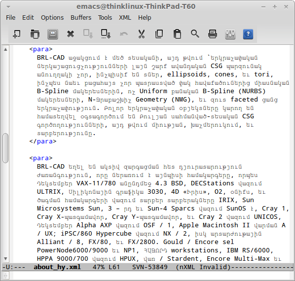
Currently, all translations are manually created and manually maintained. If you are working with translated documents, you are not limited to the ASCII character set; you can use Unicode characters in a document. The following example is the Armenian translation of the BRL-CAD introduction documentation:
Selecting Output Formats
Although you can produce HTML, UNIX man pages, and PDF files from the DocBook sources, you don't have to produce all of them. By default, PDF output is not produced because it takes longer to generate than other formats. UNIX man pages are not generated by default for Windows (where they generally are of little use) to avoid wasting configuration and compilation time.
You can use the following configuration options to turn the compilation of various formats on and off:
BRL-CAD DocBook Configuration Options
| Option |
Description |
Setting |
| BRLCAD_EXTRADOCS |
Enable DocBook documentation |
ON |
| BRLCAD_EXTRADOCS_HTML |
Enable HTML output |
ON |
| BRLCAD_EXTRADOCS_MAN |
Enable UNIX man page output |
ON (OFF on Windows) |
| BRLCAD_EXTRADOCS_PDF |
Enable PDF output (needs FOP) |
OFF |
| BRLCAD_EXTRADOCS_PDF_MAN |
Enable PDF man page output |
Defaults to setting of BRLCAD_EXTRADOCS_PDF |
The option to disable the PDF man page output exists to support situations where someone wants the article and tutorial PDFs, without the overhead of generating hundreds of PDFs for the various manual pages. If you do not specifically want PDF versions of the individual manual pages, set the BRLCAD_EXTRADOCS_PDF_MAN option to OFF.
Sharing Content Between Documents
Just as different documentation formats are needed to display the same content in different software environments, different documents that serve different needs will often need to share common content. DocBook provides a mechanism, called XInclude, which allows one document to directly reference content from another document.
For example, volume II of the BRL-CAD Tutorial Series makes extensive use of the XInclude mechanism. The majority of the original content in that tutorial was split up into individual lessons, each which exist as separate documents. To provide those individual documents and at the same time preserve the original Volume II, without duplicating content, the file BRL-CAD_Tutorial_Series-VolumeII.xml pulls in the content of the lessons using XInclude:
<xi:include href="/lessons/en/mged01_creating_primitive_shapes.xml" xpointer="creating_primitive_shapes_overviewlist"/>
For this reference to work, the lesson mged01_creating_primitive_shapes.xml must provide matching identifying labels. The matching label for the reference above is:
<para xml:id="creating_primitive_shapes_overviewlist">
The drawbacks to this mechanism are that:
- You can't read a source document as a single, coherent whole. Most of the time, content pulled into a document using XInclude should be a fairly small subset of that document unless the specific purpose of the document is to aggregate other documents.
- Content changed in one document introduces changes in other documents the author is not currently editing. Only share content with XInclude when the content is not expected to change based on the context.
Customizing DocBook Output
DocBook does not allow you to specify the formatting details of a document. This is a deliberate design decision, since avoiding the encoding of formatting information in the original document offers greater consistency and uniformity across documents.
However, some documents have unique formatting requirements. DocBook's toolchain allows you to do this type of customization, but it is the most complex aspect of working with DocBook. You should only customize the output when there is a compelling need to do so.
One of the best examples of DocBook output customization in BRL-CAD is work done by Tom Browder to format the PDF covers of the BRL-CAD Tutorial Series volumes, as shown below:
A number of elements are needed to achieve this result:
- A custom XML Stylesheet Language (XSL) file (named doc/docbook/resources/brlcad/tutorial-template.xsl.in) that defines the layout of the document.
- A custom CMake build logic file (name doc/docbook/books/en/CMakeLists.txt) that further customizes the template file for each individual book.
- The Deja-Vu and STIX fonts (located in doc/docbook/resources/other/fonts) to ensure uniform, high-quality text rendering.
Although each case of special formatting is likely to be unique, the preceding example can serve as a starting point. Another useful resource for information about customizing DocBook output is the book DocBook XSL: The Complete Guide (http://www.sagehill.net/docbookxsl).
Now that you have an idea about how to format documentation for the BRL-CAD project, let's take a look at the types of documentation that the project maintains.
How to Contribute
Developing code for BRL-CAD becomes easier when you understand how to obtain and modify the code.
Obtaining the Code
You can get the development code for BRL-CAD from our Subversion code repository using the following command:
svn checkout svn://svn.code.sf.net/p/brlcad/code/brlcad/trunk brlcad-code
The code will be saved in your /home directory, and you can compile it by following the instructions HACKING file located in top-level code directory. That said, the following are a few useful tips to help get you going.
Obtaining the Development Tools
BRL-CAD uses the CMake build system and will compile with most compilers. Download CMake and install it. If necessary, compile it from the source code.
Configuring the Environment
Next, set up the build directory and configure the compilation. At compilation time, BRL-CAD considers most warnings to be errors, so it's best if you lower the level of error logging to debug. To do that, run the following command:
cmake ../brlcad_build -DBRLCAD_BUILD_TYPE=Debug
Compiling BRL-CAD
It will take anywhere from a few minutes to one hour to compile BRL-CAD, depending on your hardware. Run the following commands to compile the software:
make; make test;
If the build fails, run make again and capture the output to a log file by running the following command:
make >build.log 2>&1
Note: If you have a quad-core CPU, you can run make -j4 to request compilation in parallel.
Installing BRL-CAD
Depending on the version of the source code that you started with, BRL-CAD should install into the following folder:
/usr/brlcad/SUBDIR
Where SUBDIR is either rel-version or dev-VERSION.
Performing a Quick Test
You don't have to install BRL-CAD. Instead, you can just run the binaries that are found in the brlcad_build/bin directory by running the following commands:
bin/benchmark; bin/mged ;
That's it! If you have a Release compile, you can submit your benchmark results to benchmark@brlcad.org.
Discussing Code
After obtaining the source code, you should to join the BRL-CAD developer mailing list (http://lists.sourceforge.net/lists/listinfo/brlcad-devel) and the #brlcad IRC channel at irc.freenode.net.
Joining both lists helps introduce yourself to the BRL-CAD community and gives you the opportunity to regularly communicate with other experienced contributors. You can also ask questions on the mailing list or the IRC channel.
Note that BRL-CAD contributors have a set of rules that they try to respect and follow to enable collaboration and communication. We strongly encourage new contributors to be creative and to be specific when asking questions on the mailing list or on the IRC channel. We also strongly advise you to use interleaved posting when replying on any communication channels. And never be afraid to ask questions.
Finally, when modifying code, it's advisable to regularly consult with experienced developers and to follow these rules of thumb when adding changes:
- Test your code to ensure that the change is correct.
- Document your changes clearly and succinctly to ensure that others understand the change.
- Write tests for your change so others can use them when testing subsequent changes.
- Make a handful of patches and submit them to SourceForge for review.
- Obtain commit access.
Code Example: Shooting Rays
Shooting rays at models is one of the more common operations performed with BRL-CAD models. The following example illustrates how to use librt's C API to shoot a ray at a model and how to work with the results.
#include "common.h"
#include <stdlib.h>
#include <math.h>
#include <string.h>
#include <stdio.h>
#include "vmath.h"              /* vector math macros */
#include "raytrace.h"           /* librt interface definitions */
/**
 * rt_shootray() was told to call this on a hit.
 *
 * This callback routine utilizes the application structure which
 * describes the current state of the raytrace.
 *
 * This callback routine is provided a circular linked list of
 * partitions, each one describing one in and out segment of one
 * region for each region encountered.
 *
 * The 'segs' segment list is unused in this example.
 */
HIDDEN int
hit(struct application *ap, struct partition *PartHeadp, struct seg *UNUSED(segs))
{
    /* iterating over partitions, this will keep track of the current
     * partition we're working on.
     */
    struct partition *pp;

    /* will serve as a pointer for the entry and exit hitpoints */
    struct hit *hitp;

    /* will serve as a pointer to the solid primitive we hit */
    struct soltab *stp;

    /* will contain surface curvature information at the entry */
    struct curvature cur = RT_CURVATURE_INIT_ZERO;

    /* will contain our hit point coordinate */
    point_t pt;

    /* will contain normal vector where ray enters geometry */
     vect_t inormal;

    /* will contain normal vector where ray exits geometry */
    vect_t onormal;

    /* iterate over each partition until we get back to the head.
     * each partition corresponds to a specific homogeneous region of
     * material.
     */
    for (pp=PartHeadp->pt_forw; pp != PartHeadp; pp = pp->pt_forw) {

        /* print the name of the region we hit as well as the name of
         * the primitives encountered on entry and exit.
         */
        bu_log("\n--- Hit region %s (in %s, out %s)\n",
               pp->pt_regionp->reg_name,
               pp->pt_inseg->seg_stp->st_name,
               pp->pt_outseg->seg_stp->st_name );

        /* entry hit point, so we type less */
        hitp = pp->pt_inhit;

        /* construct the actual (entry) hit-point from the ray and the
         * distance to the intersection point (i.e., the 't' value).
         */
        VJOIN1(pt, ap->a_ray.r_pt, hitp->hit_dist, ap->a_ray.r_dir);

        /* primitive we encountered on entry */
        stp = pp->pt_inseg->seg_stp;

        /* compute the normal vector at the entry point, flipping the
         * normal if necessary.
         */
        RT_HIT_NORMAL(inormal, hitp, stp, &(ap->a_ray), pp->pt_inflip);

        /* print the entry hit point info */
        rt_pr_hit("  In", hitp);
        VPRINT(   "  Ipoint", pt);
        VPRINT(   "  Inormal", inormal);

        /* This next macro fills in the curvature information which
         * consists on a principle direction vector, and the inverse
         * radii of curvature along that direction and perpendicular
         * to it.  Positive curvature bends toward the outward
         * pointing normal.
         */
        RT_CURVATURE(&cur, hitp, pp->pt_inflip, stp);

        /* print the entry curvature information */
        VPRINT("PDir", cur.crv_pdir);
        bu_log(" c1=%g\n", cur.crv_c1);
        bu_log(" c2=%g\n", cur.crv_c2);

        /* exit point, so we type less */
        hitp = pp->pt_outhit;

        /* construct the actual (exit) hit-point from the ray and the
         * distance to the intersection point (i.e., the 't' value).
         */
        VJOIN1(pt, ap->a_ray.r_pt, hitp->hit_dist, ap->a_ray.r_dir);

        /* primitive we exited from */
        stp = pp->pt_outseg->seg_stp;

        /* compute the normal vector at the exit point, flipping the
         * normal if necessary.
         */
        RT_HIT_NORMAL(onormal, hitp, stp, &(ap->a_ray), pp->pt_outflip);

        /* print the exit hit point info */
        rt_pr_hit("  Out", hitp);
        VPRINT(   "  Opoint", pt);
        VPRINT(   "  Onormal", onormal);
    }

    /* A more complicated application would probably fill in a new
     * local application structure and describe, for example, a
     * reflected or refracted ray, and then call rt_shootray() for
     * those rays.
     */

    /* Hit routine callbacks generally return 1 on hit or 0 on miss.
     * This value is returned by rt_shootray().
     */
    return 1;
}
/**
 * This is a callback routine that is invoked for every ray that
 * entirely misses hitting any geometry.  This function is invoked by
 * rt_shootray() if the ray encounters nothing.
 */
HIDDEN int
miss(struct application *UNUSED(ap))
{
    bu_log("missed\n");
    return 0;
}
int
main(int argc, char **argv)
{
    /* Every application needs one of these.  The "application"
     * structure carries information about how the ray-casting should
     * be performed.  Defined in the raytrace.h header.
     */
    struct application  ap;

    /* The "raytrace instance" structure contains definitions for
     * librt which are specific to the particular model being
     * processed.  One copy exists for each model.  Defined in
     * the raytrace.h header and is returned by rt_dirbuild().
     */
    static struct rt_i *rtip;

    /* optional parameter to rt_dirbuild() that can be used to capture
     * a title if the geometry database has one set.
     */
    char title[1024] = {0};

    /* Check for command-line arguments.  Make sure we have at least a
     * geometry file and one geometry object on the command line.
     */
    if (argc < 3) {
        bu_exit(1, "Usage: %s model.g objects...\n", argv[0]);
    }

    /* Load the specified geometry database (i.e., a ".g" file).
     * rt_dirbuild() returns an "instance" pointer which describes the
     * database to be raytraced.  It also gives you back the title
     * string if you provide a buffer.  This builds a directory of the
     * geometry (i.e., a table of contents) in the file.
     */
    rtip = rt_dirbuild(argv[1], title, sizeof(title));
    if (rtip == RTI_NULL) {
        bu_exit(2, "Building the db directory for [%s] FAILED\n", argv[1]);
    }

    /* Display the geometry database title obtained during
     * rt_dirbuild if a title is set.
     */
    if (title[0]) {
        bu_log("Title:\n%s\n", title);
    }

    /* Walk the geometry trees.  Here you identify any objects in the
     * database that you want included in the ray trace by iterating
     * of the object names that were specified on the command-line.
     */
    while (argc > 2)  {
        if (rt_gettree(rtip, argv[2]) < 0)
            bu_log("Loading the geometry for [%s] FAILED\n", argv[2]);
        argc--;
        argv++;
    }

    /* This next call gets the database ready for ray tracing.  This
     * causes some values to be precomputed, sets up space
     * partitioning, computes bounding volumes, etc.
     */
    rt_prep_parallel(rtip, 1);

    /* initialize all values in application structure to zero */
    RT_APPLICATION_INIT(&ap);

    /* your application uses the raytrace instance containing the
     * geometry we loaded.  this describes what we're shooting at.
     */
    ap.a_rt_i = rtip;

    /* stop at the first point of intersection or shoot all the way
     * through (defaults to 0 to shoot all the way through).
     */
    ap.a_onehit = 0;

    /* Set the ray start point and direction rt_shootray() uses these
     * two to determine what ray to fire.  In this case we simply
     * shoot down the z axis toward the origin from 10 meters away.
     *
     * It's worth nothing that librt assumes units of millimeters.
     * All geometry is stored as millimeters regardless of the units
     * set during editing.  There are libbu routines for performing
     * unit conversions if desired.
     */
    VSET(ap.a_ray.r_pt, 0.0, 0.0, 10000.0);
    VSET(ap.a_ray.r_dir, 0.0, 0.0, -1.0);

    /* Simple debug printing */
    VPRINT("Pnt", ap.a_ray.r_pt);
    VPRINT("Dir", ap.a_ray.r_dir);

    /* This is what callback to perform on a hit. */
    ap.a_hit = hit;

    /* This is what callback to perform on a miss. */
    ap.a_miss = miss;

    /* Shoot the ray. */
    (void)rt_shootray(&ap);

    /* A real application would probably set up another ray and fire
     * again or do something a lot more complex in the callbacks.
     */

    return 0;
}
Types of Documentation We Maintain
BRL-CAD provides developers, users, and others with a range of documentation covering the basics of the software, its usage, and development APIs. This chapter briefly introduces the types of documentation that the BRL-CAD project maintains, as well as the purpose of each document.
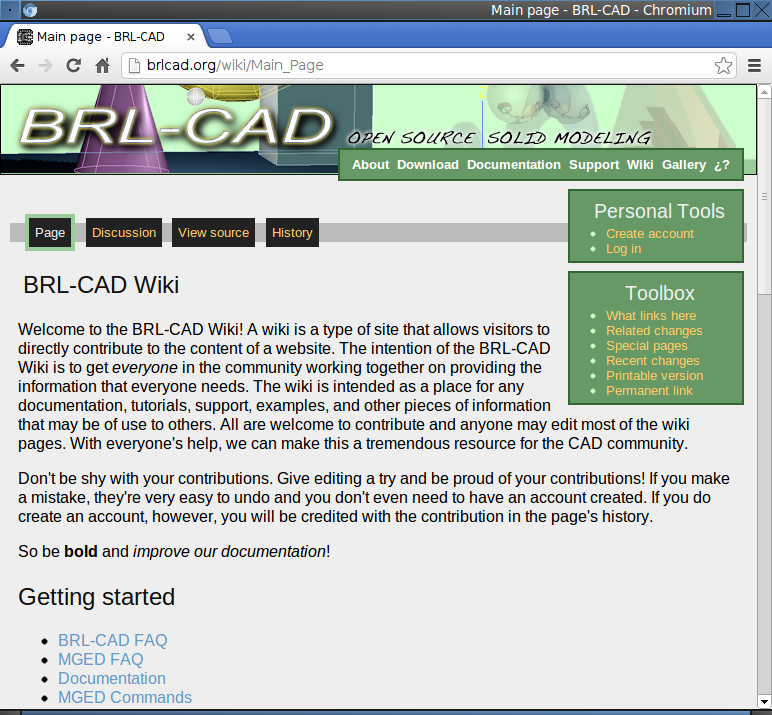
BRL-CAD Wiki
The easiest way to contribute as a documenter is through BRL-CAD's wiki (a website that users can edit) at http://brlcad.org/wiki/Main_Page. The wiki is not currently integrated with any of the other documentation systems in BRL-CAD, although this remains one of BRL-CAD's project goals.
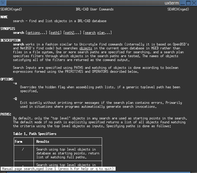
Man Pages
Man pages are command-specific or program-specific documentation which thoroughly document and demonstrate the use of that command or program. Man pages may reference other man pages, but they are intended to be the primary source of documentation for a specific tool and should be written with a very tight focus.
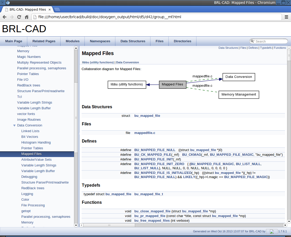
API Documentation
Most of the project's documentation is maintained in the BRL-CAD source code repository as DocBook files (see the chapter Working with Our Documentation for more information about DocBook). API documentation, on the other hand, is automatically generated from the headers in the application's source code. Specially formatted source code comments in the headers are converted to HTML documentation by Doxygen (http://www.doxygen.org), a tool for generating source code documentation.
API documentation is the lowest level, most authoritative documentation of BRL-CAD's programming interfaces. However, it does not address user-level programs or commands.
Lessons
Lessons are documents that are used to train a user to master a particular aspect of BRL-CAD. Unlike other documents, lessons focus on step-by-step teaching.
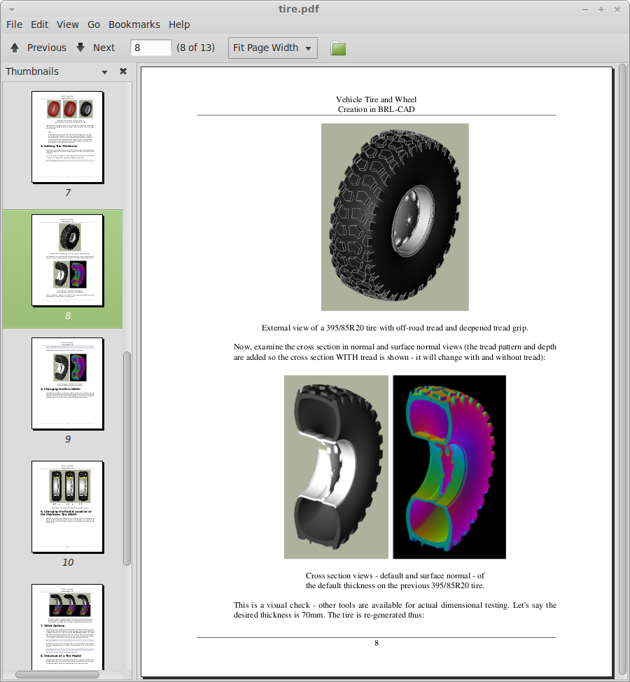
Reports and Articles
These can be technical reports, journal articles, conference papers, and/or similar focused descriptions of specific aspects of the package. Unlike lessons, reports and articles are primarily designed to inform rather than train. They are generally less comprehensive in scope and/or detail than a full-blown book.
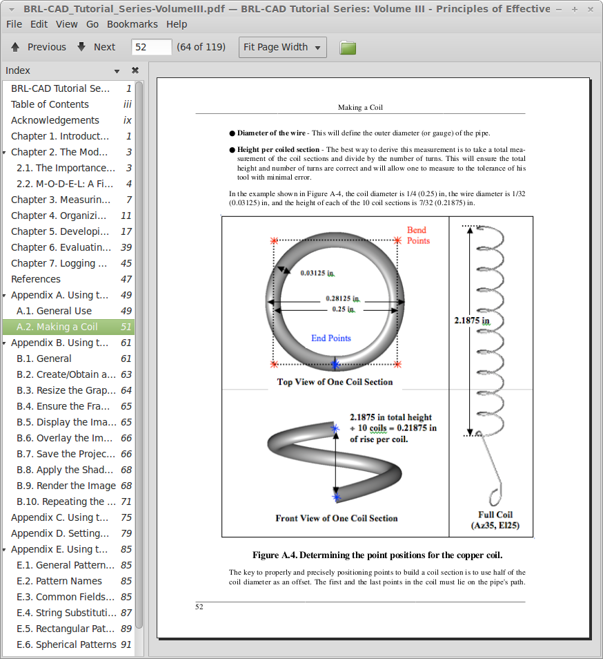
Books
Books are typically large documents that cover many aspects of BRL-CAD. In some cases, books can be collections of lessons, reports, articles, and/or other forms of documentation that are compiled between one set of covers.
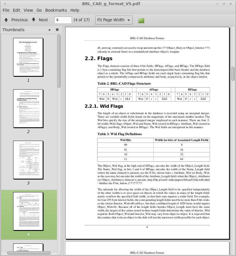
Specifications
Specifications are formal documents that define formats or protocols that others can independently implement. Currently, the only specification in the BRL-CAD documentation set is a draft specification of the .g file format.
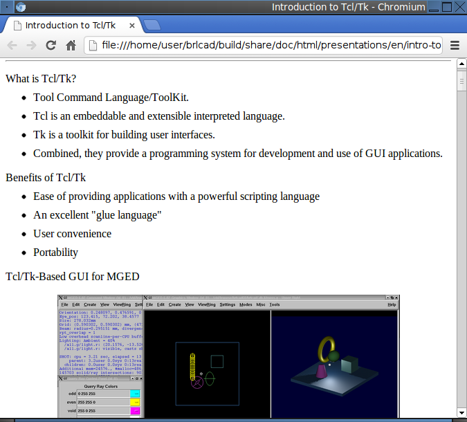
Presentations
Presentations can range from an overview of the entire BRL-CAD package to an in-depth review of a specific feature or technical algorithm. Presentations are often used when marketing or explaining some aspect of BRL-CAD to people who are not familiar with it.
What Documentation to Work On
If you would like to work on a major project, then this section is for you. Depending on how much you want to participate, we have documentation tasks that you can tackle and complete in a short or longer time. In any case, you are invited to work on the documentation for BRL-CAD forever.
Like our development tasks, the documentation tasks that we have available can take you anywhere from two hours to two days to two or more weeks to complete.
Two-Hour Tasks
If you want to get started working on the BRL-CAD documentation immediately, one great way to do that is by helping to clean up the existing documentation. Take a look at the documentation and check the spelling or copy edit it to make the documentation more concise or to correct problems with grammar or punctuation. Alternatively, check out our list of documentation tasks (http://brlcad.org/wiki/Deuces#Documentation_and_Training) that you can complete in two hours or less.
Two-Day Tasks
If you have a little more time to devote to the documentation, we maintain a list of tasks that will take you anywhere from a few hours to a few days to complete. You can find that list on the BRL-CAD website (http://brlcad.org/wiki/Contributor_Quickies). These tasks have roughly the same complexity and require no prior experience with BRL-CAD.
We also have a list of bugs in our BUGS file. While most of the bugs in the list focus on the BRL-CAD code, there are a few related to the documentation. If you plan to tackle a documentation bug, remember to report it in our bug tracker (http://sourceforge.net/p/brlcad/bugs/).
Two-Week Tasks
If you are familiar with CAD in general and BRL-CAD in particular, then you might want to try creating some tutorial and training material. Check out our list of training material that we need (http://brlcad.org/wiki/Contributor_Quickies#Training).
What Code to Work On
If you would like to fix a bug or work on a major project, then this section is for you. Depending on how long you want to be with us, we have tasks that will take you anywhere from a few hours to a few days to several months to complete. Regardless of your level of participation, make sure you read the How to Contribute section for information about BRL-CAD's developer guidelines.
Two-Hour Tasks
These tasks have roughly the same complexity and require no prior experience with BRL-CAD experience to complete. They're a great starting point for anyone interested in getting involved in the development process of BRL-CAD, as they can be completed in just a couple of hours.
Check out our list of available mini tasks that we call deuces and quickies. Each task has a labelled level of difficulty: easy, medium, and hard. Although the hard ones are math intense, don't let them scare you away.
Two-Week Tasks
If you have few hours to spare each day, check our TODO list (http://brlcad.org/xref/source/TODO). These tasks can help potential developers do modifications and submit patches to gain commit access to our code repository. You should be able to complete the tasks on this list within 14 days. Before starting on a task, however, you should discuss it with other developers on our mailing list.
We also have a BUGS file, included in each binary and source distribution, which lists the application bugs that developers are invited to fix. If you plan to tackle a bug, remember to report it in our bug tracker.
Students participating in Google Code-in can view tasks on the BRL-CAD website (http://brlcad.org/wiki/GCI_Tasks). Each task is described in a little detail, and students are directed to relevant BRL-CAD source code or websites to help them complete these tasks.
Two-Month Tasks
If you want to become more deeply involved in the BRL-CAD project, then you should take the time to check our ideas page (http://brlcad.org/~sean/ideas.html). Students who are participating in Google Summer Of Code should explore our projects page (http://brlcad.org/~sean/ideas.html) and the ideas page to get a feel for the tasks that are available. These tasks should take about 60 days to complete.
You Can Help Too
So you don't code or write documentation? That doesn't matter. You can still contribute to the BRL-CAD project. Other areas in which we need help with include:
- Bug Reporting and Feature Requests
- Outreach and Artwork
- Quality Assurance
- Research
- Translations
- User Experience
Most of the tasks in these areas don't require deep technical skills, but they are definitely important. They need your time, your commitment, and your passion. If find any of these areas interesting, then BRL-CAD has a place for you.
Let's take a look at a few other ways that you can contribute to the BRL-CAD project.
Bug Reporting and Feature Requests
Finding bugs in software is often a challenging task for developers. If you find a problem with the software, file a bug report on BRL-CAD's official bug tracking page on SourceForge (http://sourceforge.net/p/brlcad/bugs/). Please remember to provide enough detail so that we can reproduce the problem. You can also post to our developer mailing list at brlcad-devel@lists.sourceforge.net.
In addition, if you have a suggestion for new feature, feel free to submit a request on BRL-CAD's official feature request page (http://sourceforge.net/p/brlcad/feature-requests/) on SourceForge. You can also post to our developer mailing list at brlcad-devel@lists.sourceforge.net.
Outreach and Artwork
BRL-CAD has a large and passionate community of users and contributors. We need people to work with that community and to help with marketing and promoting the software.
As well, we need professional-quality artwork. Everything from logos to diagrams to icons. And just about anything in between. Your efforts will help give BRL-CAD a more polished look and will support our outreach and marketing efforts.
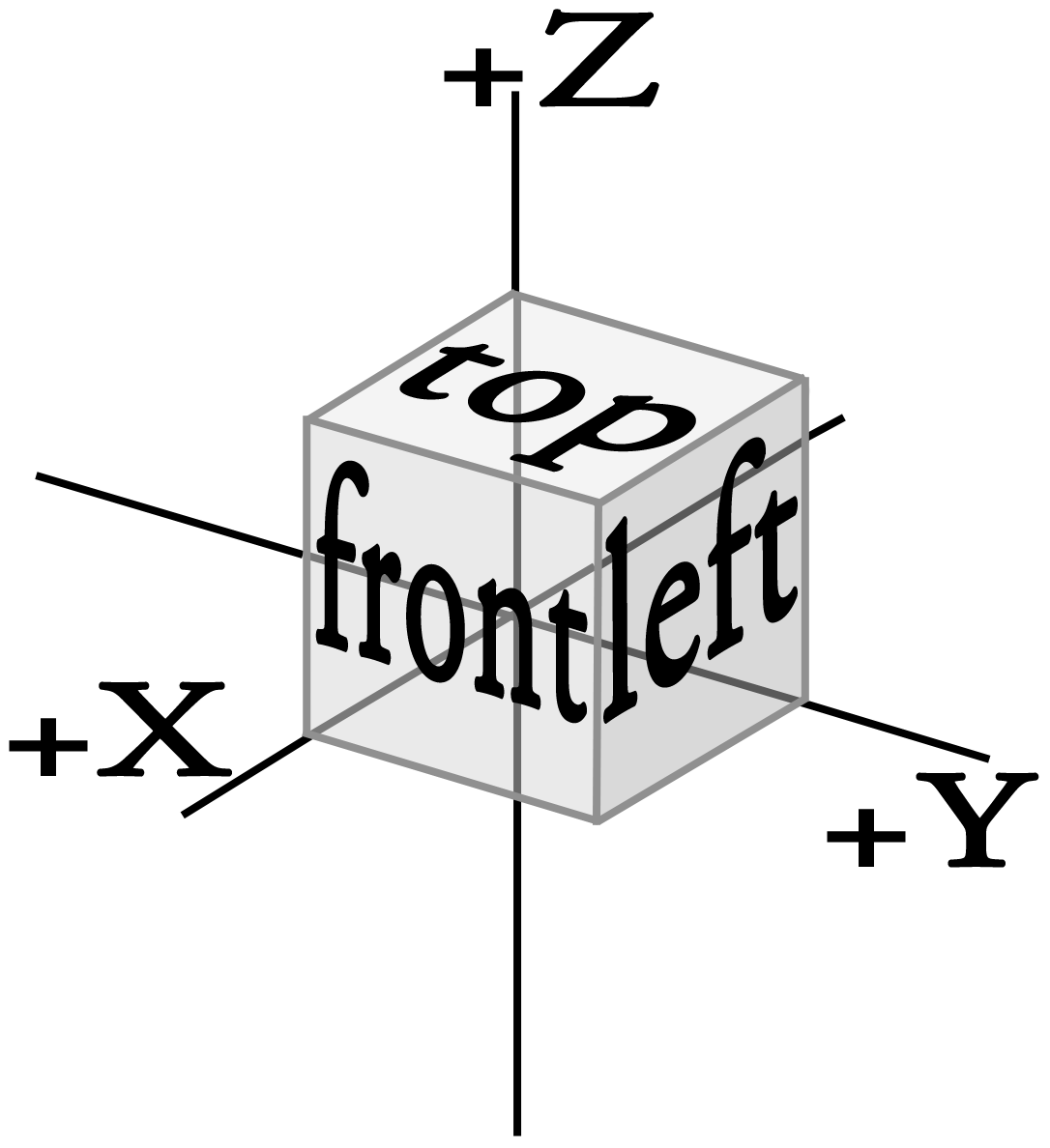
The preceding diagram was created to illustrate BRL-CAD's coordinate system.
You can find a list of outreach and artwork tasks that will get you started at the BRL-CAD website (http://brlcad.org/wiki/Contributor_Quickies#Outreach).
Quality Assurance
Testing is a vital part of the software development process. As Eric Raymond said, "given enough eyeballs, all bugs are shallow." We need your eyeballs to help us ensure that the code for BRL-CAD is of the highest quality.
What can you do? Create testing frameworks and tests for specific portions of the code. Or go through BRL-CAD's graphical user interface and find and report any bugs. You can help make BRL-CAD better by reporting any problems you encounter.
You can find a list of quality assurance tasks that will get you started at the BRL-CAD website (http://brlcad.org/wiki/Contributor_Quickies#Quality_Assurance).
Research
BRL-CAD improves not just through rigorous coding and quality assurance but also through research. We need contributors who can study problems with the software and recommend solutions based on their research. This is an area which typically requires a solid level of technical ability, but contributions here can have an enormous positive impact on the software.
You can find a list of research tasks that will get you started at the BRL-CAD website (http://brlcad.org/wiki/Contributor_Quickies#Research).
Translations
We want to make BRL-CAD available to as many users as possible, regardless of what language they speak. To that end, we're steadily making the software available in a number of languages. But there's still work to do. If you have a knowledge or one or more languages other than English, we can use your skills.
You can find a list of translation tasks that will get you started at the BRL-CAD website (http://brlcad.org/wiki/Contributor_Quickies#Translation).
User Experience
BRL-CAD is a large, powerful, and complex piece of software. And as with any software package, it can always be made more consistent, usable, and user friendly. If you're willing to learn the user interface and to approach the package with a critical eye, then you can help make the BRL-CAD user interface friendlier and more consistent.
You can find a list of user experience tasks that will get you started at the BRL-CAD website (http://brlcad.org/wiki/Contributor_Quickies#User_Interface).