


Mesh Editing Quickstart
Important - Make sure you understand the Blender Interface before going on with this chapter.
For those of you that simply want to get started modeling your own projects, I'm going to give coverage of basic techniques common to most 3D modeling software. Later on, I'll take you through the process of making a model step by step using some of these techniques.
First, ensure you have an object in your scene. If you don't have one yet, add a Cube (see Interface section for how) or just use the default Cube that Blender provides when you start it up.
Selection Modes
Hit the A Key on your object to ensure that no vertices, faces or edges are selected. A deselected face is blue in colour.
Note that in the bottom of the viewport - and only while in Edit Mode - are a few icons that look like this:
![]()
If you can't see these icons on the bottom of your viewport it is either because you aren't in Edit Mode or because this header at the bottom of your viewport is too short. The header of a viewport can be dragged left or right using the MMB. Try to drag the selection mode icons into view using MMB if you can't see them.
These icons represent the different kinds of mesh data we can select. The vertices have the dots icon, edges the diagonal line icon and faces the triangle icon. Note that when you select an edge you are selecting two vertices. When you are selecting a face you are selecting three or more vertices (and thus three or more edges).
Try clicking on the face selection icon. Notice how a small black square appears on each face in the cube. RMB on a given face will now cause it to become selected. When a face is selected it will become pink and the edges and vertices will become yellow.Try the same for both edge and vertex selection modes and notice how the colours of vertices and edges change when they are selected.
Multiple Faces, Edges or Vertices can be selected using the SHFT+RMB combination. Practice moving faces or edges or vertices by selecting them with the GKey and moving the mouse cursor around. LMB or ENTER will confirm the new position for the face. RMB or ESC will cancel the movement. As always, CTRL+Z-key will undo the last action.
Global and Local Axes
Many of the below editing techniques refer to the axes X, Y and Z. Before working with axes in a 3D environment it's important to remember that objects and faces can have both Local and Global axes.
Global axes are applicable to the entire scene and everything in it. They cannot be altered, just in the same way East and West in the real world don't change direction.
Local axes however represent only the orientation of an object or part of an object in question. Local axes can be thought of as being a bit like in front, behind, to the left and to the right. Local axes are relative, in that they depend upon which way the object is facing. For instance an object might have its Local X axis pointing along the Global Z axis.
Before applying a transformation (like Rotation or Scaling etc) decide whether you want to perform it using the local orientation of your selection, or the global orientation of your scene. You can change whether you're working within the Global or Local orientation using the Transform Orientation drop-down menu at the base of each viewport.
This menu is shown in the below image:
![]()
Rotating
Free Mouse rotation
Any selection of faces can be rotated using the R-key followed by free mouse movement. Naturally this is highly innacurate, especially if done in a Perspective view.
Numeric rotation
Faces can also be rotated along a given axis by a numerically defined number of degrees. To do this first select the faces you'd like to rotate, hit the R-key then hit the axis you'd like to rotate around and then enter a number of degrees.
For example, if I wanted to rotate a face around the global Z axis by 45 degrees I'd: R-key then Z-key then NUMPAD-4 then NUMPAD-5.
Important: when you rotate objects or meshes using numeric input you are rotating those parts relatively, not absolutely! For example: R-key then Y-key then 45NumPad means "rotate around the Y axis another 45 degrees".
Uniform and Non-Uniform scaling
Uniform scaling refers to the method of scaling the selection by the same amount across all axes at once. This is the default in Blender. Non-uniform scaling is the term given to selective scaling across just one or two of the axes. For example, to make an object twice as long as it is wide or high you could non-uniformly scale it along just one axis.
Uniform scaling: mouse
Doing this with the mouse is quite tricky but is very convenient once you become familiar with it. This technique involves telling Blender which axis you want to scale along using a mouse gesture.
Select all or some faces in your object (selecting all will make this excercise clearer). Now move your mouse cursor along the axis you want to scale your faces and then press the MMB down. The faces will scale along that axis only. For instance, if you wanted to scale your entire mesh only along the Y axis you'd switch to Top view (orthographic of course), move the mouse in the up-down direction and then hit MMB. As usual, ENTER or LMB will confirm the change.
Non-uniform scaling: numeric
This technique is very similar to the numeric uniform scaling above, but involves telling Blender which axis you want to scale along.
Select the faces you want to scale, hit the S-Key, choose an axis and then provide the scale multiplier number. For example: to scale twice along the Z axis you'd: S-Key then Z-key then NUMPAD-2.
Non-uniform constrained scaling: numeric
It is also possible to tell Blender to scale along all except one axis. To scale along the X and Y axes while denying scaling along Z you'd: S-key then hit SHFT+Z-key then NUMPAD-2.
Selecting Regions
Two marquee like selection modes are provided. These are especially useful for selecting vertices and/or faces in detailed meshes. They can also be used to select several objects in object mode. Naturally this technique will be most useful to you when there are many vertices in your object. Select your object and go into Edit mode.
Box Select
With your cursor over the viewport you want to select in, hit the B-key. Note that the mouse cursor changes to a cross-hair, with perpendicular dotted lines extending from it. Now you can LMB and drag a selection marquee across mesh elements of your object. ESC will exit Box select mode.
Circle Select
Hitting B-key twice enables circle select mode, enabling you to select using a circle shape instead of a square. Using the wheel on your mouse while in this mode will increase or decrease the size of this selection area. ESC will exit circle select mode.
Creating and Deleting Vertices, Edges and Faces
Deleting vertices, edges or faces.
Often in the course of editing you will want to remove elements. You may, for example, wish to remove a face but leave just the edges or just delete everything in the selection altogether. To do this simply select the area you wish to delete from and hit DEL or X-key. A popup menu will appear providing you with a list of deletion options. Choose one with the mouse or arrow-keys and hit LMB or ENTER.
Creating vertices, edges or faces without duplication.
Blender can be used to 'draw in' new mesh elements very quickly. There are several ways to do this. I will cover the most commonly used here.
Adding vertices
Holding the CTRL key down while you LMB in a viewport will add vertices under the cursor. These vertices will be connected by edges.
Adding a single face
Both edges and faces depend on vertices. Edges need two vertices to exist and faces a minumum of three. To add a single face, do one of the following:
- Select any three or four vertices and hit the F-key. A face will automatically be created.
- Select any two edges or any three contiguous edges and hit F-key. Thre non-contiguous edges will not make a face, instead you'll get a popup asking if you'd like to make an FGon (a special surface).
Adding multiple faces
Select a loop of edges and hit SHFT+F-key. By a loop of edges I mean a ring connected edges (a circle being a good example). A 'U' shape of edges cannot be used to create multiple faces:
Subdividing
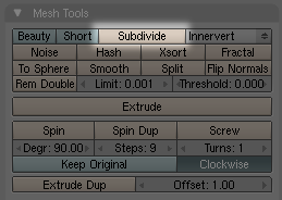
Single or multiple faces can be subdivided in a variety of different ways. First, select the faces you want to subdivide. In the Editing panel F9-key click the button subdivide.
Each time you click the subdivide button, the selected faces will be cut in half. Next to this button are a variety of subdivision types in a dropdown menu.
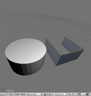
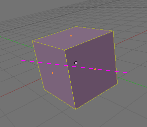
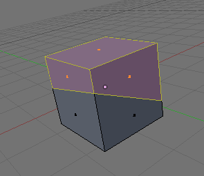
Extrusion
Extrusion is a very popular editing method used often in the practice of mesh modeling. Unlike many other methods extrusion actually adds mesh data to the original mesh. Faces, edges and even vertices can be extruded.
Note:
- If you extrude a face of 4 edges, 4 more faces will be created, once for each 'side' of the new extruded part.
- If you extrude an edge, one more face will be created.
- If you extrude a vertex, one more edge will be created.
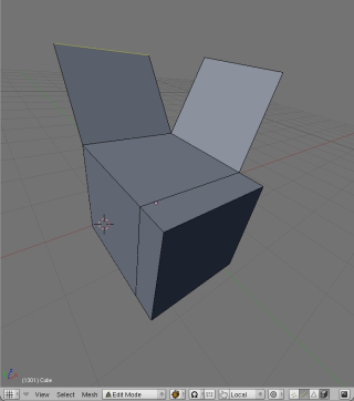
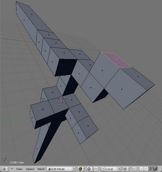
A cube with one face and two edges extruded and a subdivided cube with many faces extruded.
Extrusion: mouse
To extrude a single face, select the face and hit E-key then move the mouse. The face will extrude along the Normal (eg perpendicular to the surface of the face). Holding the CTRL key down while moving the mouse will constrain (lock) the extrusion to grid-units.Extrusion: numeric
Select a face, hit the E-key and then provide a number. For instance to extrude a face two whole grid units along its normal you'd E-key then NUMPAD-2 then ENTER to confirm the transformation.
Cutting Meshes
Often it is useful to cut one or more faces in half. For this purpose Blender provides the Knife tool. First select the faces you wish to cut and hit the K-key. You will immediately be presented with a popup menu containing several options:
- Knife (exact). This will cut the selected faces across exact points on each edge in the cut. Use this option if you want to make accurate cuts.
- Knife (midpoints). This will cut the faces once exactly in half across the midpoints of each edge in the cut. Use this option if you simply want to cut a face in half.
- Knife (multicut). This allows the user to cut the selected faces several times at once. The cuts will be at midpoints, eg. a face cut four times will produce a total of five faces of equal size.
- Knife (loop cut). This will cut all faces (selected or not) in half throughout the mesh along a local axis determined by mouse-movement. This is very useful for cutting whole meshes in half.
If you choose to make an exact, midpoints or multicut, simply click once to one side of the faces you want to cut, and again on the other side, then hit ENTER. The below images show an exact cut in use.
Before and after images of the Knife tool making an exact cut.
To make a loopcut, just move the mouse around until you see the cut you'd like and hit ENTER.
Separating ('parting') Faces
Sometimes it's useful to be able to separate a selection of faces from others in a mesh, creating a new object. To do this use the P-key.
To remember this shortcut, I like to think of 'P' as representing 'part'. New objects will be automatically given a new name based on the name of the original object. This function can be found in the Mesh->Vertices menu at the base of the viewport or under the spacebar menu.
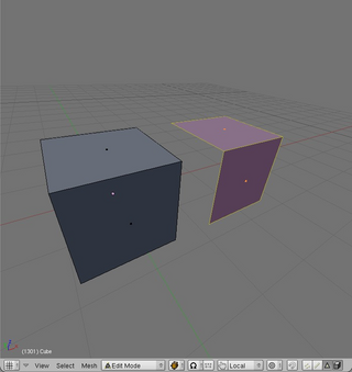
Duplication
Selected faces, edges or vertices can be quickly duplicated using SHFT+D-key. Once they have been duplicated they are automatically in grab mode, so be sure to move the mouse and place the copy elsewhere. If you don't do this, the duplication will remain exactly where the original is, and you won't know it's there!
The below image shows two faces copied from the original cube and moved one unit to the right:
Joining Objects
One object can be joined to another (thus creating a new object) using CTRL+J-key. This function can be found in the Object menu at the base of the viewport or under the spacebar menu.
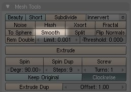
Smoothing Meshes and Surfaces
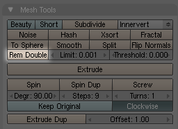
Pressing the smooth button in the Mesh Tools tab in the Editing panel will give a mesh a more organic feel by simply increasing the angles between groups of vertices. The more times you press the button the smoother the mesh will become. Naturally, the more vertices the smoother it can become. The below image shows where the Smooth button is be found.
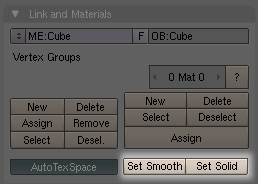
Note: Smooth is not to be confused with Set Smooth which applies a setting to the surface so that shading is averaged out across ajoining faces during rendering. Set Smooth is the opposite of the Set Solid setting, which performs no shadow averaging between faces. To make things a little confusing, this setting is also found in the Editing panel, but under the Link and Materials tab:
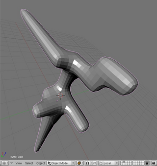
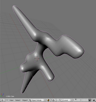
Below shows heavily subdivided version of the above extruded form mesh smoothed 10 times in both Set Solid (default) and Set Smooth surface modes:
Cleaning Up
Often in the course of editing in Blender little accidents happen that result in duplicate vertices.
One common example of how this can happen is during extrusion: you select a face to extrude and hit the E-key but change your mind, and so cancel the extrusion. You've just created an entire face sitting right ontop of the other. Another example might be that you select your entire mesh with the A-key and then duplicate it with SHFT+D-key. Instead of moving it to a new location you leave it sitting right where the original is leaving many duplicate faces (and so duplicate vertices and edges) invisible to the eye.
It's good practice to clean up these duplicate vertices using the Rem Doubles ('remove doubles') button. This function looks for vertices within a given distance from each other and if they are within this distance, it removes one of them and moves the remaining one half way between the other two. When set to a very small number (the default is fine) this can be very effective in cleaning up a mesh. The Rem Doubles button can be found just below the Subdivide button in the Mesh tools tab in the Editing (F9-key) panel.
Basic Mesh Editing
Keywords: extrusion, positioning, face creation, face duplication, low-polygon modeling, view management.
In this lesson we'll make a simple chair starting from a single plane using techniques written above in the Mesh Editing Quickstart Guide. I chose a chair for this lesson as it's is a familiar object that encompasses 3 dimensions in a way we can easily visualise (unlike spaceships, demon warriors or contemporary architecture).
Firstly ensure you have nothing in any of the three views. You can do this by either changing to another layer, or (in Object Mode) select everything with A-key and hit DEL. Now put the left viewport into Top/Orthographic view, the upper right viewport in Side/Perspective view and the bottom right viewport in Side/Orthographic view. Top/Orthographic can be thought of as a plan view, which is ideal for layouts and floorplans.
Important: when you're working in a top or side view set to Orthographic two dimensions are visible, not three. This significantly reduces confusion (and therefore error) whenever positioning objects or mesh elements with the mouse. If ever unsure check it in the View Menu in the base of each viewport.
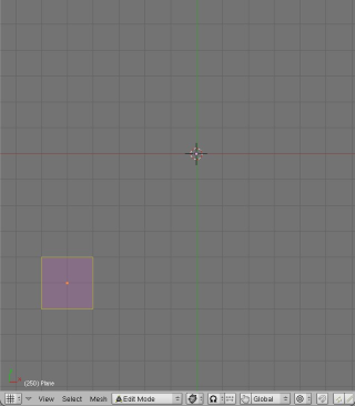
With your cursor over a viewport, center the 3D cursor with SHFT+C-key. Hit the spacebar and Add->Mesh->Plane. A plane will appear where the 3D cursor is and Blender will be in Edit Mode. This plane will become one of four legs. Choose Face Select and select that face if it isn't already.
Now we want to move that plane to the right and down a few units (x = 5, y = -5). There are three ways to do this:
Moving it with the mouse:
Hit the G-key and then hold down CTRL while moving the mouse 5 grid-units to the right and 5 down after that.
Moving it with the keyboard:
To do this numerically (ie without having to count the grid units visually), hit the G-key then X-key then type 5 on the numeric keypad and hit ENTER. Now the Y axis: G-key, Y-key- and then 5 on the numeric keypad and hit ENTER.
Important: when you move objects or meshes using keyboard input you are moving them relatively, not absolutely! In the above example we moved the plane down 5 units and across 5 units. If you want absolute positioning, use the Numeric interface (see below).
Moving it using the numeric interface:
Hit the N-key and enter the relative X and Y values manually. The advantage of the numeric interface is that we can move the objects to absolute locations.
Moving it using the 3D transform manipulator and the mouse:
Click on the 3D Transform manipulator at the base of the viewport you're working with and click on the triangle icon to allow for Translation (re-positioning). Now click the axis you'd like to move the plane along and drag with the mouse.
Note: Choose the way of moving objects most comfortable for you and use it to move objects elsewhere in the Blender tutorials.
You should now have something that looks like this in your Top view:
Now duplicate that plane with SHFT+D-key and move it along negative X by 10 units (x = -10). The new position of this plane is therefore (x = -5, y =-5).
We have two feet for our chair and we need four, so duplicate this pair of planes and move it up 10 whole grid unit. Here's what my chair looks like so far:

It's time to extrude all four of these feet to create legs. We'll do this in the Side view as we can't extrude 'upward' in the Top view. Up is along the Z axis, which is the axis not available to us in the Top view.
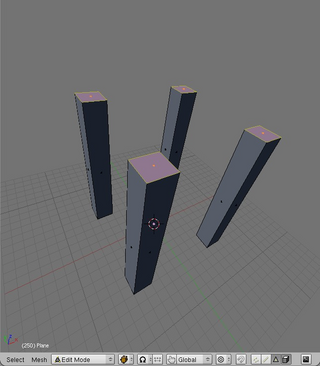
Select all the feet and in your side view hit E-key, choose Region then type 15 on the numberpad and hit ENTER. This will extrude those planes 15 grid units. This is what I have after doing this:
It's time to create some faces, so let's change the leftmost viewport into Perspective view so we can better see what we're doing. Make sure this viewport is in Solid draw mode.
With your cursor over the viewport with the Perspective view hit NUMPAD-5. If you have a small screen you can make this viewport larger by dragging over the split between viewports.
Note: Alternatively you can hit CTRL+UpArrow (or use View->Maximise Window) to maximise the viewport under the cursor. Pressing the same key combination again will take you out of maximised view. The disadvantage of a maximised view is that you can't see the Edit Panel or other viewports while in this mode.
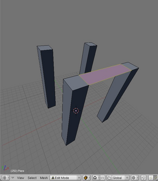
Switch to Edge Select mode and select the innermost edges at the top of two legs and hit the F-key to create a face there. It looks like this:
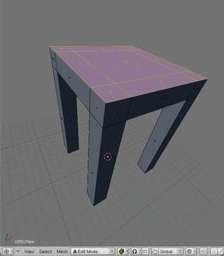
Starting with the top of the legs, create faces across the remainder of that area, so that it looks like so:
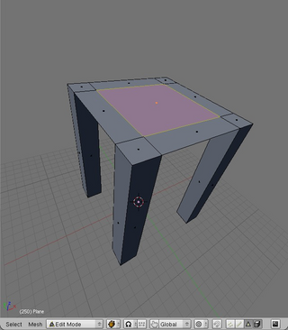
Now we have the base of the seat, so let's extrude it up. Change to Face Select mode and select all the faces on the base of the seat. Extrude them all upward by 2 grid units.
Select the two back faces at the top of the legs, and extrude them up too, by 5 grid units:
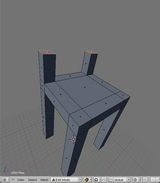
Extrude them up again, by another 2 grid units and then up again by another 5 and then finally another 2 units. You should have something that looks a bit like this:
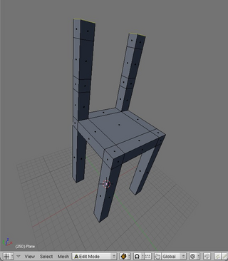
Now we'll make the back of our chair by extruding over two cross-beams. Select the two innermost square faces on one leg and extrude them over by 8 grid units along negative X so that they neatly touch the complimentary faces on the other leg. Remember that holding down CTRL while moving the mouse will constrain it to the grid. Alternatively, just use the numeric keypad (E-key then X then -8 on the numeric keypad and then ENTER).

Before we can finish we have to clean up a little. That last extrusion has created a couple of redundant faces in our mesh: we pulled over faces from one leg right ontop of another.
Select all the mesh with A-key and hit the button Rem Doubles in the Mesh Tools tab in the Edit Panel. For a description of how Rem Doubles works see Cleaning Up above.
Once done, go into Object Mode and take a look at your creation. Here's how mine turned out:
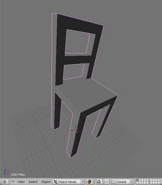
As a next step you may consider applying textures in Blender and then texture your chair. Head over to the Texturing section to learn how to do this..