


Using the FontForge drawing tools
Designing a font in FontForge will involve using a number of tools and utilities, starting with the set of drawing tools that enable you to draw your glyphs on screen. They may feel familiar to users with experience in vector graphics, but there are enough differences that some orientation is a good idea for all new users.
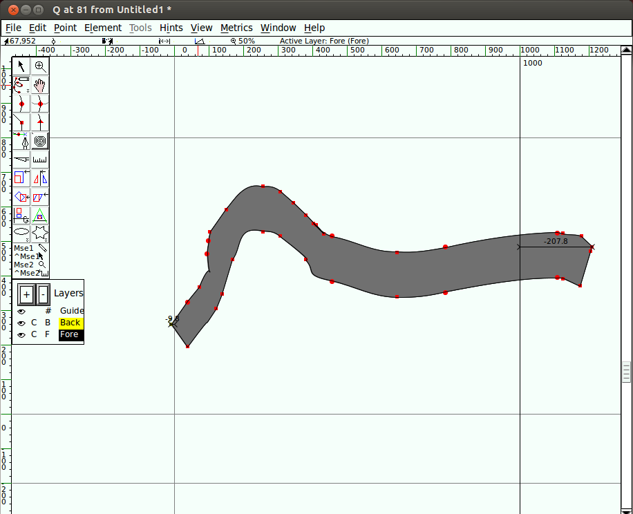
From the Font Window, double-click one of the glyph boxes to launch the Glyph Window.
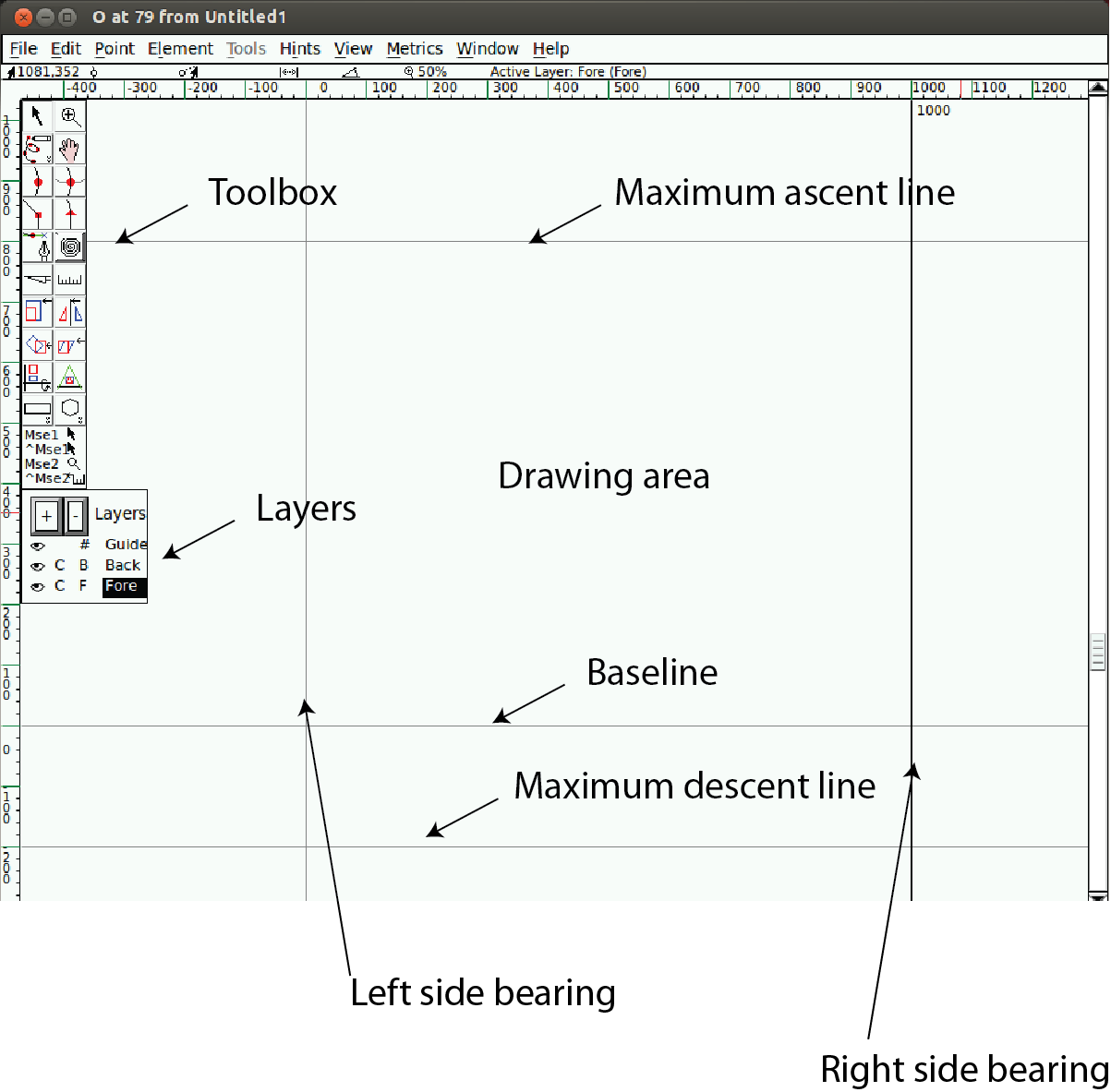
Note: The numbers along the top where the x and y axis intersect indicate the current (x,y) location of your cursor on the canvas, followed by the location of the most recently selected point. The third number is the relative position of your cursor to the selected point. The fourth number is the distance between your cursor and the selected point. Fifth is the angle from the selected point to the cursor (relative to the baseline). Next is the current magnification level, followed by the name of the active layer.
Caution: Sometimes it seems like FontForge is not responding when you are in the Glyph Window. What might be occurring is that there is an open dialog box hidden behind the Glyph Window. You will then have to move the Glyph Window to see the dialog, dismiss it, and return to the Glyph Window.
Familiarize yourself with the drawing tools
Now that you know your way around the canvas, it is time to get acquainted with the tools.
Point and zoom

Point and zoom behave similarly to the equivalent tools in any other application. The pointer is the main selection tool, used to select points, paths, and other objects on canvas. In addition to activating the pointer tool in the toolbox, you can also momentarily switch to the pointer tool while any other tool is active, simply by holding down the Control key.
The zoom tool easily lets you zoom in, but it is a bit more difficult to zoom out again. To zoom out, go to the View menu and select Zoom out or Fit.
The freehand tool
The freehand tool allows you to sketch out irregular paths. Select the freehand tool from the toolbox by clicking on this icon:
![]()
Move the freehand tool to the drawing area, hold your mouse button down, and move your mouse around to draw. Switch back to the pointer tool, and you can select points on the path you have drawn.
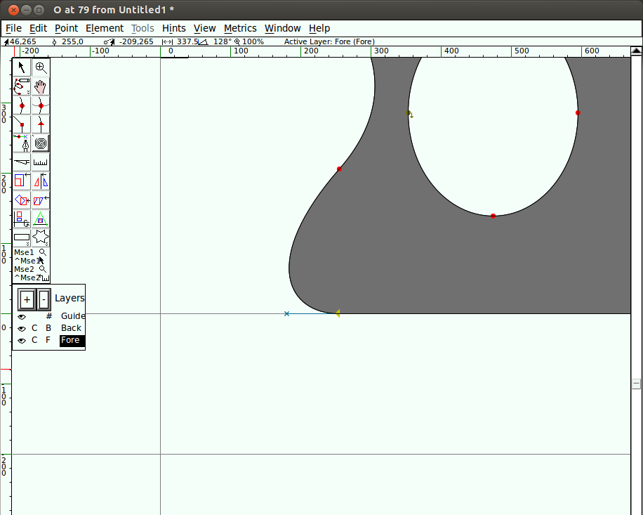
When you select one of the points on the path, it will turn into a yellow circle. If the selected point is on a curve, it will display its control points with a magenta handle and a cyan handle. You can grab either handle and drag it around to change the shape of the curve.
The point tools
Next, try using the point tools.
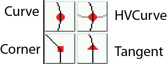
To add a point to a path, first select any of these tools, then click on the path and give it a little push. You will get a new point on the line. The Curve point tool is used to add a point in a curved segment. The HVCurve point tool constrains the new points that to add so that they have either horizontal or vertical control points. This is important for setting up extrema points. The Corner point tool allows you to make a sharp bend in the path. The Tangent point tool allows you to transition from a straight segment to a curved segment along the path.
The pen tool
![]()
The pen tool allows you to add a point on the curve and drag out its control points.
Spiro
![]()
Selecting the Spiro tool puts you into Spiro drawing mode. Spiro drawing allows you to draw curves that reflow as you reposition the nodes. Some people prefer this to the standard approach (known as Bézier editing), but if you are used to Bézier editing you might find it does some unexpected things.
Knife
![]()
The knife tool allows you to cut splines in two. This comes in handy if you have drawn a shape, but only need part of it.
Ruler
![]()
The ruler tool gives you measurement and coordinate information. When you use it, it displays a floating "tool tip" next to the cursor. If you hover your cursor over a point, the tool tip gives you even more detailed measurement and coordinate information. If you bring it next to a spline, it gives you information about the curvature and radius. Most usefully, if you click and drag the ruler tool, you will see the distance you have dragged the cursor, plus every intersection that you have stretched across.
The transform tools
There are six transform tools:
![]()
Note: For all of the Transform tools, if you double-click on the tool, you can enter numeric values.
The scale tool lets you freehand rescale an object. Holding down the Shift key allows you to scale an object while constraining it to the proportional ratio.
The rotate tool lets you free-rotate an object. It rotates the selected object around the position where you initially click the mouse.
The 3D rotate tool lets you rotate an object in the third dimension, and projects the result on the x-y plane.
The flip tool allows you to flip a selection either horizontally or vertically. The point at which you click the mouse is the point of origin of the transformation.
Note: After flipping a point you will probably want to apply Element > Correct Direction.
The skew tool lets you horizontally skew the selection either clockwise or counterclockwise (withershins is how the dialog refers to counterclockwise).
The perspective tool gives you another way to distort a shape in a nonlinear way.
Note: There is no numerical option for the perspective transformation.
The rectangle/ellipse and polygon/star tools
These tools allow you to draw primitive geometric shapes, which is faster than constructing those shapes out of separate line segments.

Clicking the chevron area on these tools will give you the option to switch to the alternate tool. If you double-click on either of the tools, you can open the shape type's options.
Rectangle options: corner style and bounding box (corner or center out).
Ellipse options: Bounding box or center out.
Polygon options: Number of vertices.
Star options: Number of star points and depth of points by percentage. The higher the percentage setting, the longer the arms of the star.
Mse1 and Mse2

Caution: This area of the toolbox seems to be broken in the most recent version of FontForge -- you may get a crash if you click in here.
Layers
The FontForge canvas has three layers by default: the Guide layer, the Background layer, and the Foreground layer. Guide layers are used to insert guides (such as x-height or cap-height guides). Foreground layers and background layers are both used for drawing, but only the topmost foreground layer will be rendered into your final font.
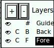
The eye icon indicates whether each layer is visible, and you can click to toggle the eye to make a layer invisible. The C (or Q) indicates whether you're using Bézier or Quadratic curves.
The #, B, or F refers to whether the type of each layer is a Guide layer, Background layer, or Foreground layer, which is significant if you add more layers of your own. You can create and delete additional layers using the plus (+) or minus (-) buttons in this section of the toolbar. Layer type and curve type can also be controlled by right-clicking (once you have additional layers).
Basic Drawing
Next you should walk through some of the basic drawing workflows you will use over and over.
Correct Direction
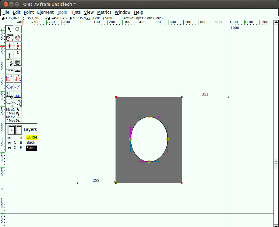
- Start by using the Rectangle tool to draw a rectangle within the drawing area of the Glyph window.
- Next, use the Ellipse tool to draw an ellipse within the rectangle you just drew.
- Go to the Element menu and choose Correct Direction. You will see that the two shapes merged, and that you essentially punched a hole in the center of the rectangle.
Remove Overlap
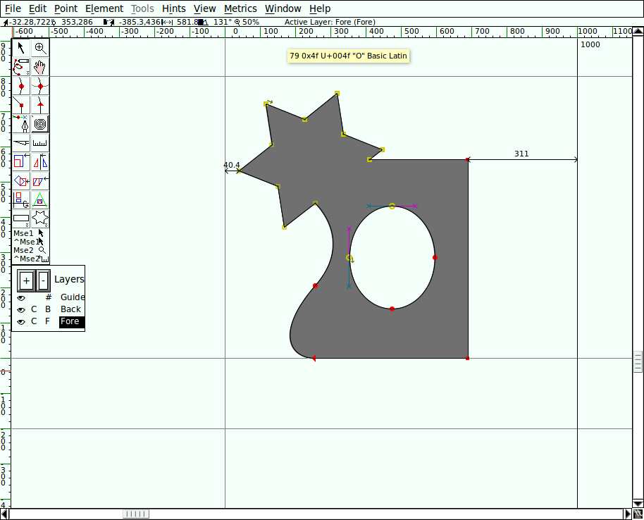
- Add a star that overlaps the corner of the rectangle.
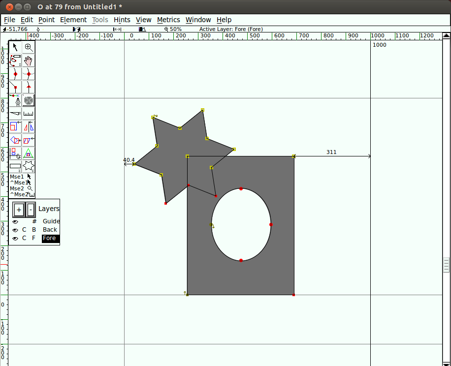
- Select the star and the earlier shape. You only need to select one point of each overlapping shape, but it is okay to select extra points.
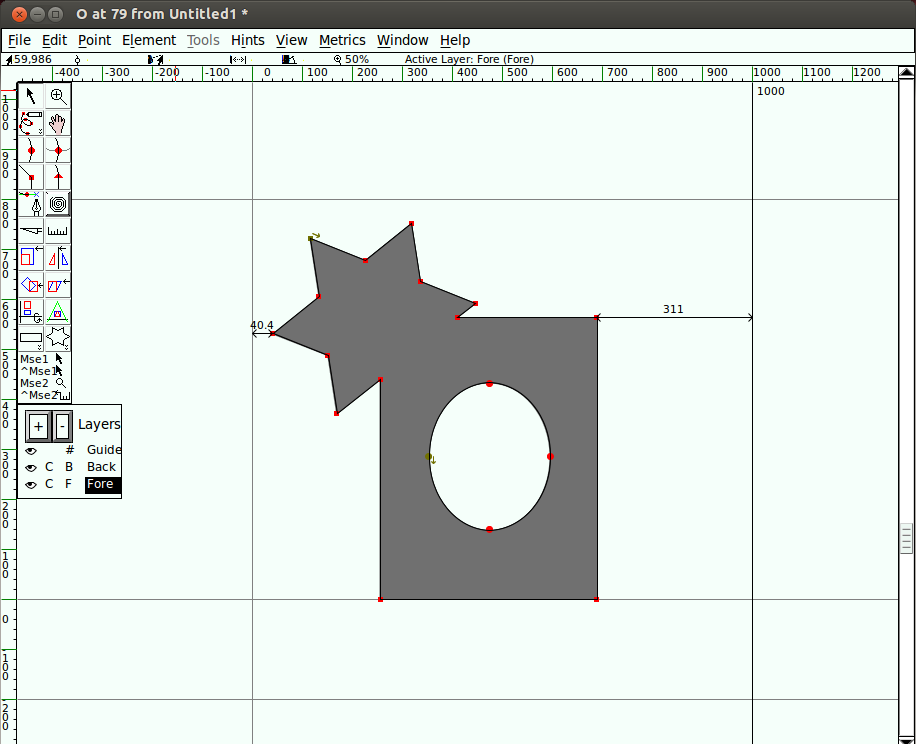
- Go to Element > Overlap > Remove overlap. You will see that your two shapes have become one.
Add a Point
Using the pen tool, click and hold in the middle of a line segment. Keeping the mouse button clicked, drag the mouse to change the shape.
Tangent points
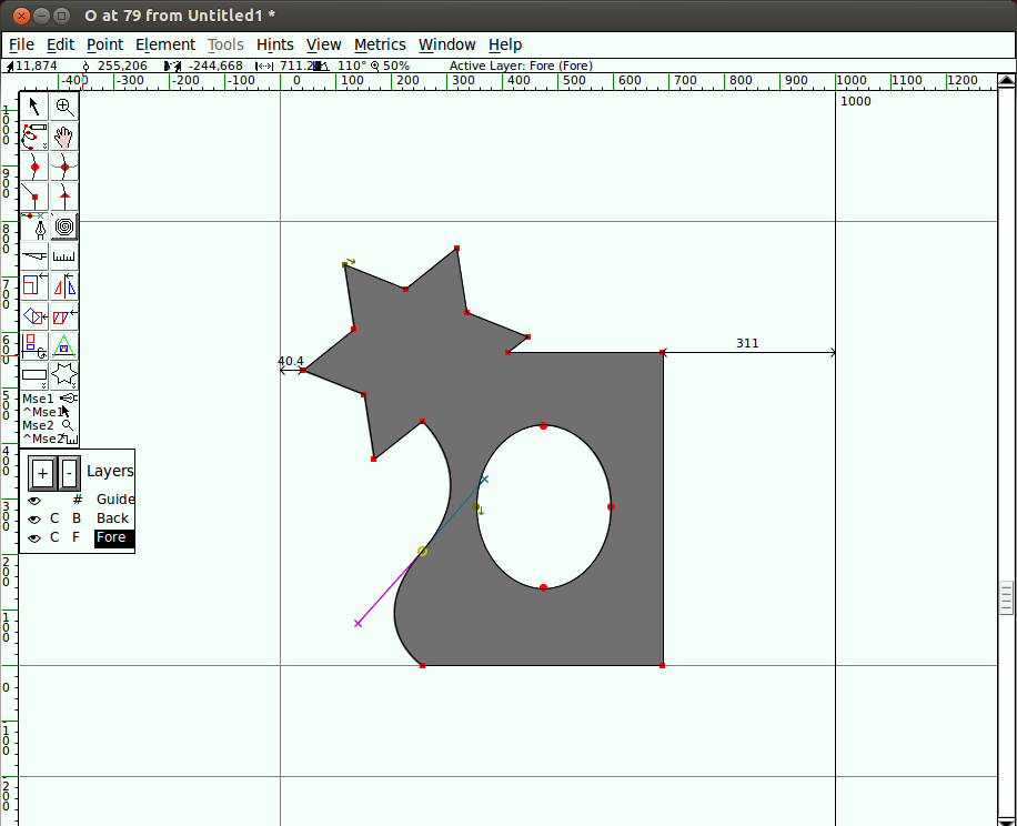
Select the bottom-left corner point of your new shape (the intersection of the curve and the straight line). From the Point menu, you will see that Corner Point is checked. Select Tangent. This changes the square node to a triangle, but that is all it does until you do the next step: extending control points.
To do so, choose Element > Get Info, which opens the Point Info Window. From the Location tab in that window, go to the Next CP field set and set the Distance to a large number such as 75. Click OK. You will see that the curve now smoothly enters the straight line.
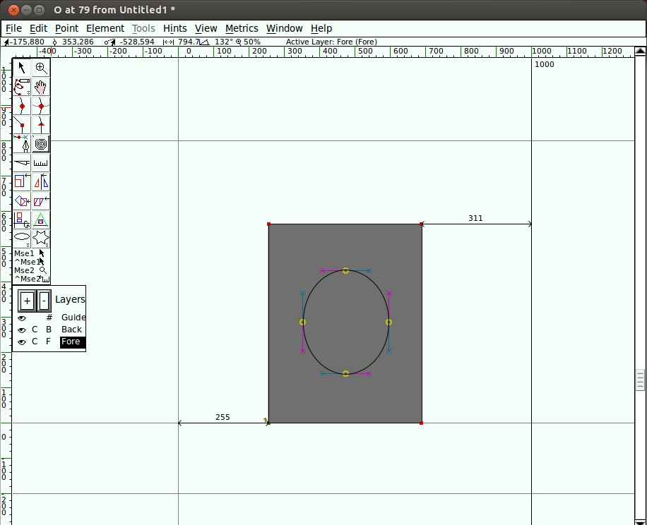
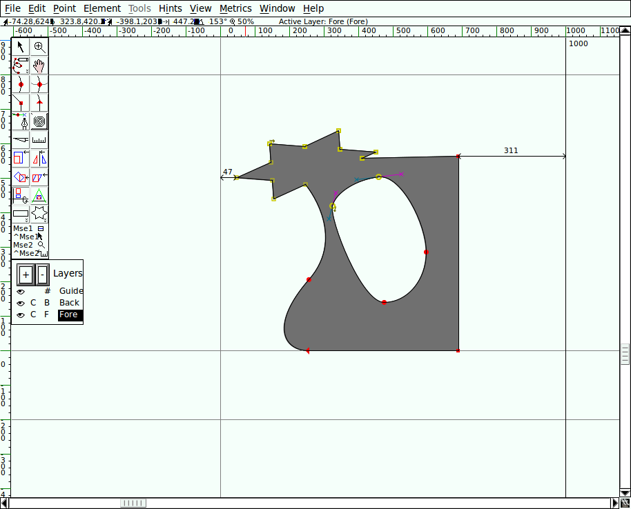
Transformation
Now select about a quarter of the shape -- the star and part of the ellipse in the middle.
Choose the 3D Rotate tool, mouse to the middle of the selected area, and slowly click and drag until you see something you like, then release. Here is an example of 3D Rotate used on the practice image:
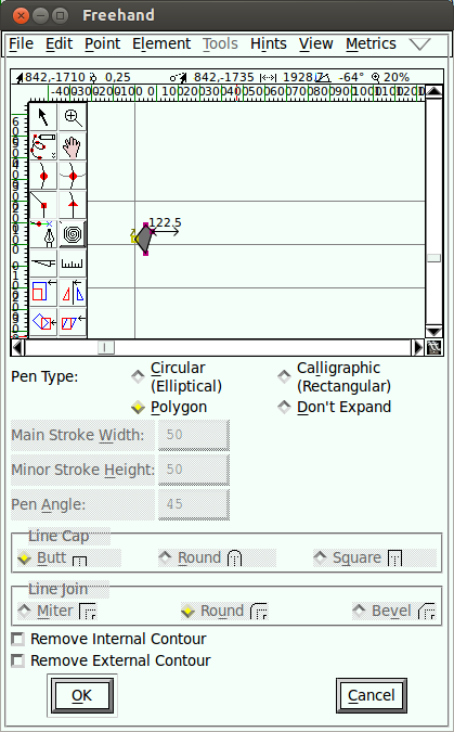
Set stroke shape and width
So far you have used the Freehand drawing tool to draw a line. If you double-click the Freehand tool, you get the Freehand dialog shown here, which contains a drawing window. This is where you select pen shape and size. This dialog also appears when you choose the Expand Stroke option in the Element menu.
Using the corner tool, draw a polygon and click ok.
Now draw a line with the Freehand drawing tool. When you release the mouse button, the new path is automatically stroked with the shape you chose in the Freehand dialog, as shown here.
Keep drawing
You should continue to experiment with the drawing tools until you feel comfortable that you can use them to draw and transform whatever shapes you need. At this point, you are equipped to start constructing the components of glyphs, but you should also take time to look at FontForge's other set of tools, Spiro drawing mode. Spiro drawing is distinct enough from Bézier curve editing that it requires an explanation of its own.