Connector Tool
The Connector tool (Ctrl+F2 or the o key) draws lines between objects that stay connected to other objects as they are manipulated. Any object may be marked as an object to avoid, which causes connectors to automatically route around the object. This is helpful for creating technical illustrations like flowcharts.
How to Use
Connecting
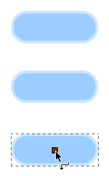
A new connector can be drawn by clicking and dragging from any point on the canvas. Connectors can also be created with two clicks, rather than click-and-drag, if this is preferred. In this case, click once on an empty point on the canvas to begin drawing the connector, then move the mouse to the new connector's target point and then click again to finalize the connector. Single clicking on a canvas object selects/deselects that object, just as with other tools. Usually connectors are drawn from an existing object:

Connection point handles are shown while the mouse cursor is hovering over a non-connector object in the connector tool. Currently they are shown only at the center of objects. When creating a connector, if the connector is started or ended over a connection point then the connector will be attached to that object. From then on the connector will be automatically rerouted whenever the attached object is moved.
Connectors attached to objects are currently drawn to the bounding box of those objects. It is planned that they will be drawn instead to the edges of objects.
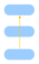
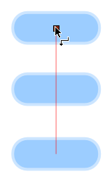
The connector is finalized, when the mouse is released:

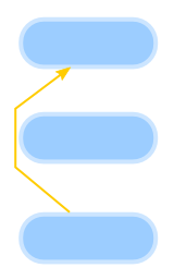
The Make connectors avoid selected objects button marks all objects in the selection as "avoided", causing all current and future connectors to automatically avoid these objects.
The Make connectors ignore selected objects button marks all objects in the selection as "ignored", causing all current and future connectors to completely ignore these objects. This is the default for all canvas items, i.e., no objects are automatically routed around by default.
Here the middle object is avoided:
By default, the Connector tool will not attach connectors to text objects. A checkbox in the Connector preferences controls this setting.
Rerouting
A selected connector shows two endpoint handles. By clicking and dragging these, the connector can be rerouted and attached/detached from objects.
Connectors moved as part of a selection will stay attached to other objects in the selection, rather than becoming detached from them.
Arranging
The margins around avoided shapes used for autorouting connectors can be adjusted via the "Spacing" control on the controls bar.
The Remove Overlaps button to move the selected objects enough that they don't overlap each other. A minimum spacing between the boundaries of objects can be specified. Together with the automatic layout tool, described above, this should be a significant addition to Inkscape's usability for diagramming. Removing overlaps is different from the "Unclump" button in that the former is completely deterministic and guarantees removing overlaps on the first application, but is not concerned with visual perceptive distances between objects. Unclumping, on the other hand, attempts to equalize perceptive distances between objects and can be applied repeatedly for gradual effect.
Automatic Diagram Layout: this function is available in the Align and Distribute dialog and performs automatic layout of diagrams involving a network of shapes and connectors. Edges are treated as if they are springs such that the distance between nodes will be proportional to the path length — number of connectors — between them. Disconnected components (where not every shape is connected) will be arranged around the circumference of a circle.


